
Laser spot welding of overlapping aluminum workpieces

a technology of aluminum workpieces and laser welding, which is applied in the field of laser welding, can solve the problems of difficult autogenous fusion welding of aluminum workpieces, difficult to break apart and disperse coatings, and the use of laser welding to join together aluminum workpieces, etc., to achieve satisfactory strength, promote greater disturbance, and promote the effect of smoother transition

Inactive Publication Date: 2018-10-25
GM GLOBAL TECH OPERATIONS LLC
View PDF0 Cites 10 Cited by
  • Summary
  • Abstract
  • Description
  • Claims
  • Application Information

AI Technical Summary

Benefits of technology

The patent describes a laser welding method for joining aluminum workpieces that creates a strong and sound weld joint. The method involves using a laser beam to create a molten aluminum weld pool that penetrates the workpiece stack-up from the top surface towards the bottom surface. The power density of the laser beam is selected to vaporize the aluminum workpieces and create a keyhole directly underneath the laser beam within the weld pool. The keyhole provides a conduit for energy absorption deeper into the workpiece stack-up, which facilitates deeper and narrower penetration of the weld pool. The depth of penetration of the keyhole may be different along nonlinear inner and outer weld paths. The method also involves advancing the laser beam along the spot weld travel pattern to minimize weld defects and promote greater disturbance of the protective anti-corrosion coating. The strength of the weld joint can be enhanced by remelting and resolidifying a peripheral portion of the weld joint with the laser beam or advancing the laser beam first along the outer weld path and then in a direction from the innermost nonlinear inner weld path or weld path portion.

Problems solved by technology

The use of laser welding to join together aluminum workpieces, however, can present challenges.
But the presence of the protective anti-corrosion coating also makes it more challenging to autogenously fusion weld aluminum workpieces together by way of laser welding.
The protective anti-corrosion coating is believed to affect the laser welding process by contributing to the formation of weld defects in the final laser weld joint.
When, for example, the protective anti-corrosion coating is a passive refractory oxide coating, the coating is difficult to break apart and disperse due to its high melting point and mechanical toughness.
As a result, near-interface defects such as residual oxides, porosity, and micro-cracks are oftentimes found in the laser weld joint.
These zinc vapors may, in turn, diffuse into and through the molten aluminum weld pool created by the laser beam and lead to entrained porosity in the final laser weld joint unless provisions are made to vent the zinc vapors away from the weld site, which may involve subjecting the workpiece stack-up to additional and inconvenient manufacturing steps prior to welding.
The other materials mentioned above that may constitute the protective anti-corrosion coating can present similar issues that may ultimately affect and degrade the mechanical properties of the weld joint.
Such mechanical fasteners, however, take much longer to put in place and have high consumable costs compared to laser weld joints.
They also increase manufacturing complexity and add extra weight to the part being manufactured—weight that is avoided when joining is accomplished by way of autogenous fusion laser welds—that offsets some of the weight savings attained through the use of aluminum workpieces in the first place.

Method used


Image

  • Laser spot welding of overlapping aluminum workpieces
  • Laser spot welding of overlapping aluminum workpieces
  • Laser spot welding of overlapping aluminum workpieces

Examples


Embodiment Construction

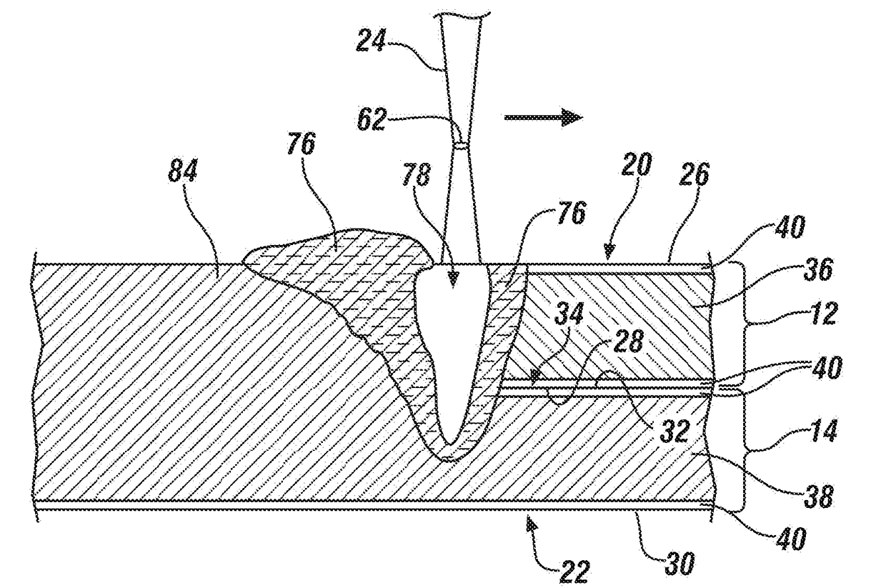
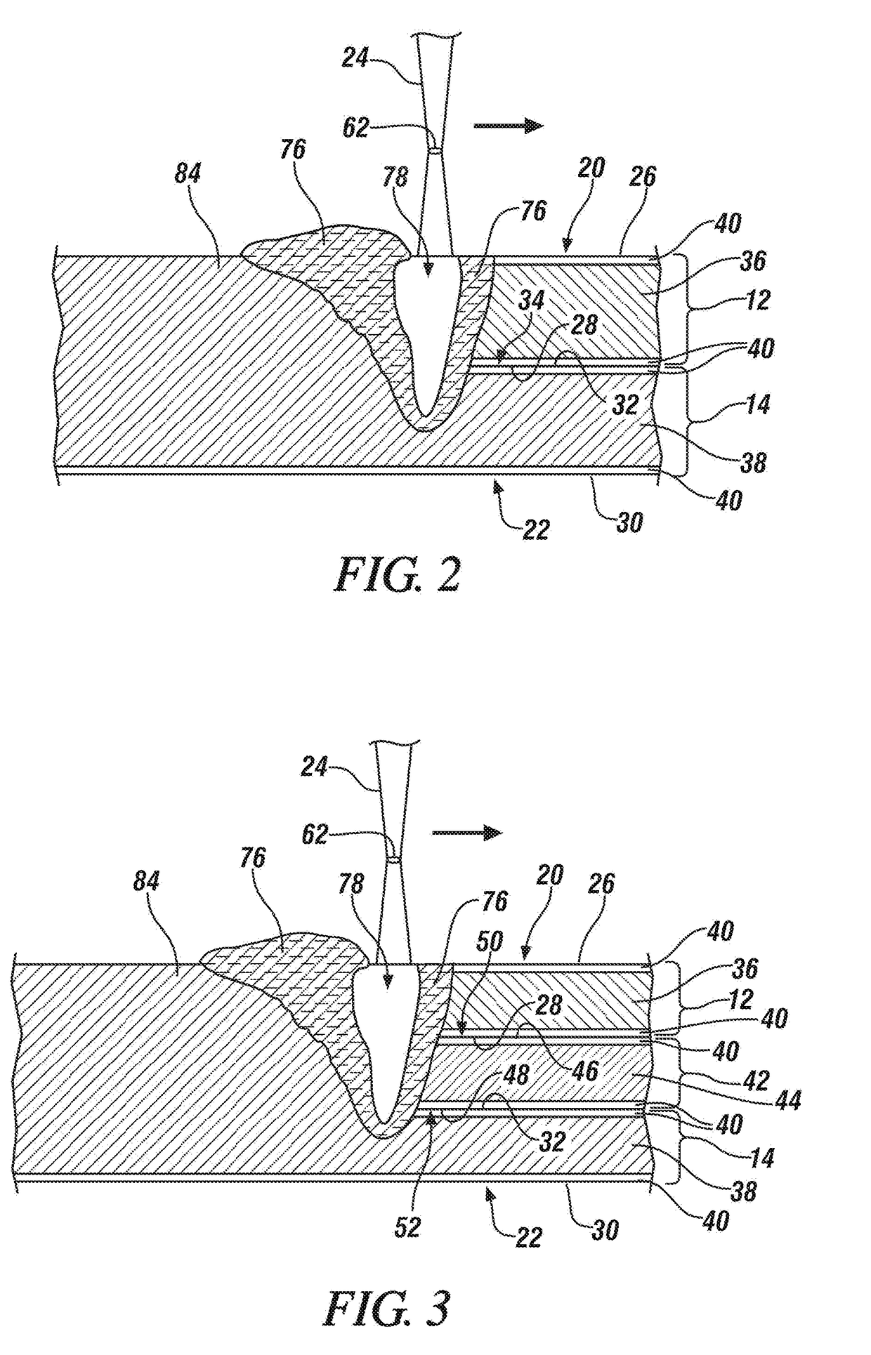
[0027]The disclosed method of laser welding a workpiece stack-up comprised of two or more overlapping aluminum workpieces calls for advancing a laser beam relative to a plane of a top surface of the workpiece stack-up along a spot weld travel pattern. The disclosed spot weld travel pattern includes one or more nonlinear inner weld paths surrounded by a peripheral outer weld path. Any type of laser welding apparatus, including remote and conventional laser welding apparatuses, may be employed to advance the laser beam relative to the top surface of the workpiece stack-up. The laser beam may be a solid-state laser beam or a gas laser beam depending on the characteristics of the aluminum workpieces being joined and the laser welding apparatus being used. Some notable solid-state lasers that may be used are a fiber laser, a disk laser, and a Nd:YAG laser, and a notable gas laser that may be used is a CO2 laser, although other types of lasers may certainly be used so long as they are abl...


PUM

PropertyMeasurementUnit
focal lengthaaaaaaaaaa
boiling pointaaaaaaaaaa

Abstract

A method of laser welding a workpiece stack-up (10) that includes at least two overlapping aluminum workpieces (12, 14) comprises advancing a laser beam (24) relative to a plane of a top surface (20) of the workpiece stack-up (10) and along a spot weld travel pattern (74) that includes one or more nonlinear inner weld paths and an outer peripheral weld path that surrounds the one or more nonlinear inner weld paths. Such advancement of the laser beam (24) along the spot weld travel pattern (74) translates a keyhole (78) and a surrounding molten aluminum weld pool (76) along a corresponding route relative to the top surface (20) of the workpiece stack-up (10). Advancing the laser beam (24) along the spot weld travel pattern (74) forms a weld joint (72), which includes resolidified composite aluminum workpiece material derived from each of the aluminum workpieces (12, 14) penetrated by the surrounding molten aluminum weld pool (76), that fusion welds the aluminum workpieces (12, 14) together.

Description

TECHNICAL FIELD[0001]The technical field of this disclosure relates generally to laser welding and, more particularly, to a method of laser spot welding together two or more overlapping aluminum workpieces.BACKGROUND[0002]Laser spot welding is a metal joining process in which a laser beam is directed at a metal workpiece stack-up to provide a concentrated energy source capable of effectuating a weld joint between the overlapping constituent metal workpieces. In general, two or more metal workpieces are first aligned and stacked relative to one another such that their faying surfaces overlap and confront to establish a faying interface (or faying interfaces) within an intended weld site. A laser beam is then directed at a top surface of the workpiece stack-up. The heat generated from the absorption of energy from the laser beam initiates melting of the metal workpieces and establishes a molten weld pool within the workpiece stack-up. The molten weld pool penetrates through the metal ...

Claims


Application Information

Patent Timeline
Patent Type & Authority Applications(United States)
IPC IPC(8): B23K26/22B23K26/082B23K26/32
CPCB23K26/22B23K2103/10B23K26/082B23K26/32
Inventor YANG, DAVID S.ZHANG, JINGTAO, WUWOLSKER, JUSTIN A.
Owner GM GLOBAL TECH OPERATIONS LLC
Learn More