Device, system and method for in-situ optical monitoring and control of extraction and purification of plant materials

a technology of optical monitoring and control, applied in the direction of optical radiation measurement, evaporator regulation/control, separation processes, etc., can solve the problems of toxic or even carcinogenic exposure to these chemicals, insignificant trace amounts, and inability to detect the presence of toxic chemicals

Active Publication Date: 2018-10-25
AROMETRIX INC
View PDF23 Cites 7 Cited by
  • Summary
  • Abstract
  • Description
  • Claims
  • Application Information

AI Technical Summary

Benefits of technology

[0097]In the above method, the optically transparent tube may be tilted so that the liquid flows due to the effect of gravity. Furthermore, the device which is mounted onto the optically transparent tube may include various combinations of features (a1)-(a20) described above.

Problems solved by technology

Frequently the essential oils and concentrates that get extracted from the plant can be contaminated with toxic chemicals, including heavy metals, microbes, pesticides and other hazardous compounds that get transferred from the original plant and further concentrated into the extract.
Exposure to these chemicals has been proven toxic or even carcinogenic.
Even when the pesticides are undetectable on the plant itself, they frequently become concentrated during the extraction process, and the trace amounts are magnified.
The judgment is also highly susceptible to quality of the feedstock, which is often inconsistent.
Results of these arbitrary actions are reduced product yield and process productivity, reduced product purity and / or contaminated products.
High fogginess, turbidity, stronger colorization or drift from the light yellow color are all signs of reduced quality.

Method used


Image

  • Device, system and method for in-situ optical monitoring and control of extraction and purification of plant materials
  • Device, system and method for in-situ optical monitoring and control of extraction and purification of plant materials
  • Device, system and method for in-situ optical monitoring and control of extraction and purification of plant materials

Examples


Embodiment Construction

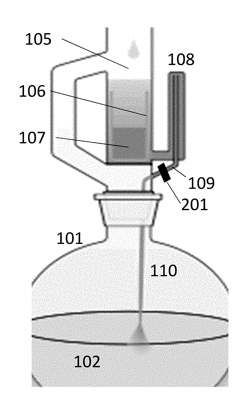
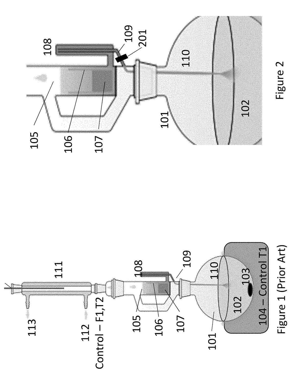
[0121]FIG. 1 shows the schematic of a typical prior art Soxhlet extractor used in plant processing. The source plant material 107 containing the bio-compound to be extracted is placed inside the thimble 106. The thimble 106 is loaded into the main chamber of the Soxhlet extractor 105. The extraction solvent 102 is placed in a distillation flask 101. The distillation flask is heated by the heating element 104 and stirred by the mechanical stirrer 103. The main chamber of the Soxhlet extractor 105 is placed atop the flask 101. A reflux condenser 111 is placed atop the extractor 105 and is cooled through coolant inlet 112 and coolant outlet 113. The coolant is typically water. The evaporated solvent 102 is condensed in the condenser 111 and fills the main chamber of the Soxhlet extractor 105 housing the thimble 106. The bio-compound 110 is dissolved from the plant material 107 by the solvent 102, fills the siphon up to the siphon top 108, and flows back into the flask 101 through the t...


PUM

PropertyMeasurementUnit
angleaaaaaaaaaa
wavelengthsaaaaaaaaaa
wavelengthaaaaaaaaaa

Abstract

In-situ optical spectroscopic monitoring, characterization and feedback control of extraction and purification processes of compounds such as oils, alkaloids, flavonoids, terpenes and cannabinoids derived from plant material are described. Liquids from an extraction or purification process flow down an optically transparent tube, such as one made of glass. An in-situ optical monitoring assembly is configured to be mounted onto the tube to measure optical properties of the liquid extract or liquid condensate as it flows in the tube. Optical properties of the flowing liquid may include optical transmittance, reflectance, photoluminescence, scattering, absorbance, turbidity, nephelometry, polarimetry and colorimetry. The output of the optical monitoring assembly can be used to display spectral and other about the flowing liquid, set alarms to notify an operator of a predetermined condition such as a set point, and used to control extraction or purification process.

Description

FIELD OF THE INVENTION[0001]The present disclosure relates to methods and systems for in-situ monitoring of extraction and purification of chemical and bioactive compounds from plant and plant-like materials.BACKGROUND OF THE INVENTION[0002]The extracts from plant materials are a rich source of compounds used in many industries such as nutraceutical, pharmaceutical and therapeutic industries. Many of the phytochemicals from plants or plant-like sources have been reported to have an impact on human and animal health. For example, high content of flavonoids in medicinal plants have been associated with their antioxidant activities that play a role in the prevention of age-related diseases.[0003]Plant materials include a varied group of plant parts from one or different / mixed plant species. Categories of plant material include, but not limited to, grass, flowers, herbs, rushes, barks, woods, gourds, stems, roots, nuts, acorns, bulbs, seeds, fruits, leaves, etc. Plant-like organisms are...

Claims


Application Information

Patent Timeline
Patent Type & Authority Applications(United States)
IPC IPC(8): G01N21/25G01N21/64G01N33/00B01D3/42B01D11/02C11B3/12
CPCG01N21/255G01N21/645G01N33/0098B01D3/42B01D11/0207B01D11/0296C11B3/12C11B1/00C11B9/025G01N21/01G01N21/05G01N21/21G01N21/251G01N21/53G01N21/85B01D1/0082B01D1/14B01D1/0088B01D3/02B01D5/006G01J1/0271G01J3/0291
Inventor METTING, CHRISTOPHER J.BUNN, JONATHAN K.COLLINS, TIMOTHY G.VON BREDOW, HASSOATANASOFF, GEORGE
Owner AROMETRIX INC
Why Eureka
Try Eureka