Method for the deposition of functional layers suitable for heat receiver tubes

Inactive Publication Date: 2018-11-01
RIOGLASS SOLAR SCH SL
View PDF6 Cites 2 Cited by
  • Summary
  • Abstract
  • Description
  • Claims
  • Application Information

AI Technical Summary

Benefits of technology

The present patent application describes a coating method that can be used with different types of deposition techniques, such as DC and MF sputtering technology. This method allows for the creation of uniform, repeatable and durable coatings for use in solar technology. The technical effect of this invention is its versatility and practicality, making it applicable to a wide range of deposition methods.

Problems solved by technology

The optimum conditions may be unstable.
The performance of reactive sputtering is, however, impeded by the effect of target “poisoning”, resulting in a significantly reduced sputter yield and, thereby, a reduced deposition rate.
However, the use of RF power supply, as source for sputtering of dielectrics to form cermet or Anti-Reflective (AR) layers, presents some disadvantages and limitations like the following:low deposition rate of dielectrics and limited power supply level (up to 30 kW compared to more than 250 kW for DC sputtering) resulting in a low productivity; andlow thickness uniformity.
Regarding the use of reactive MF sputtering for the deposition of dielectrics, trouble shootings are found such as non-uniformity of the thickness when operated in transition mode, or limited life of the target when operated in compound mode.
Particularly, when a heat receiver tube is coated by reactive MF sputtering in the solar technical field, the major limitations are as follows:poor temperature durability in metallic mode, andlow uniformity of the oxidation level.

Method used


Image

  • Method for the deposition of functional layers suitable for heat receiver tubes
  • Method for the deposition of functional layers suitable for heat receiver tubes

Examples


example 1

ic Layer)

[0119]A functional layer of Al2O3 was prepared by the method of the invention.

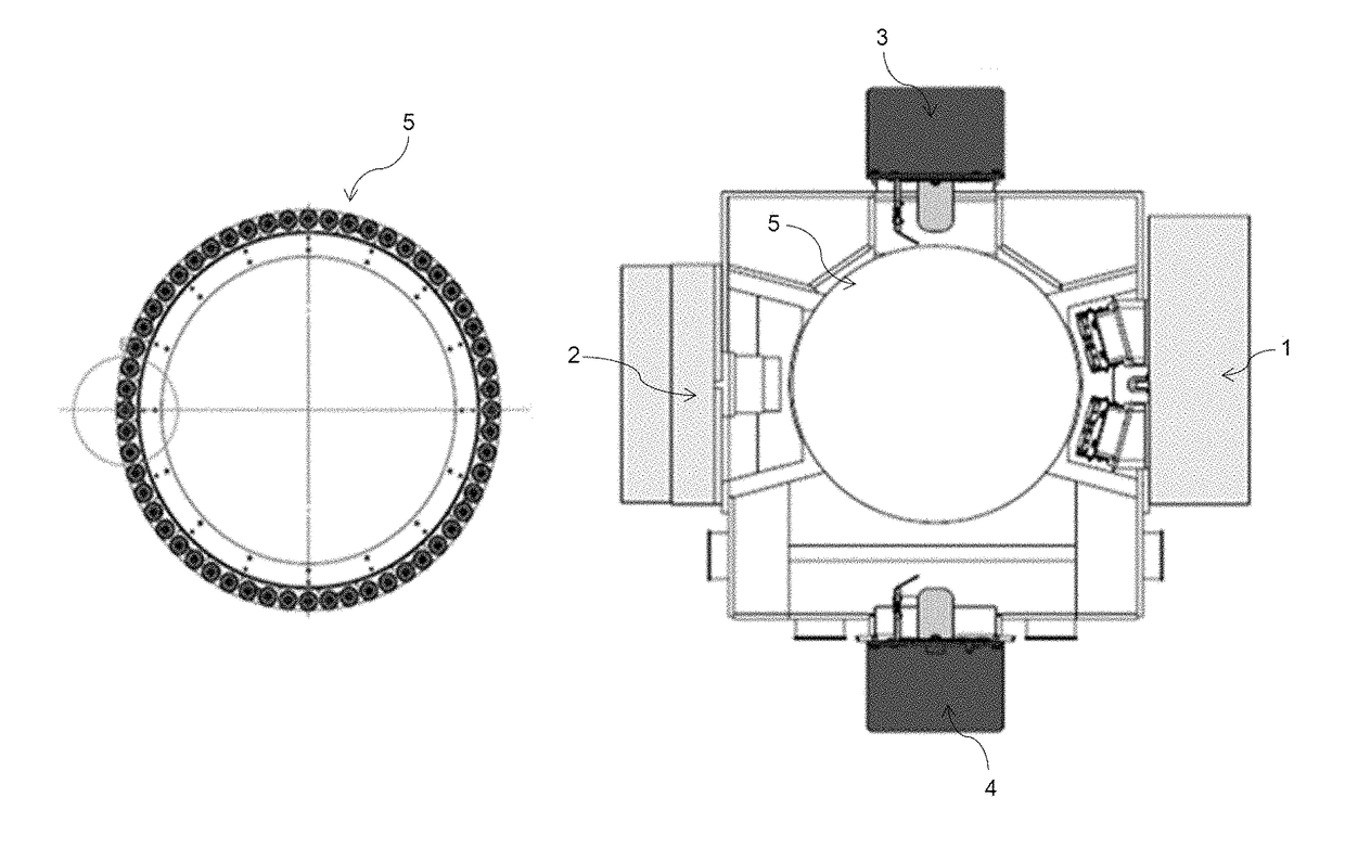
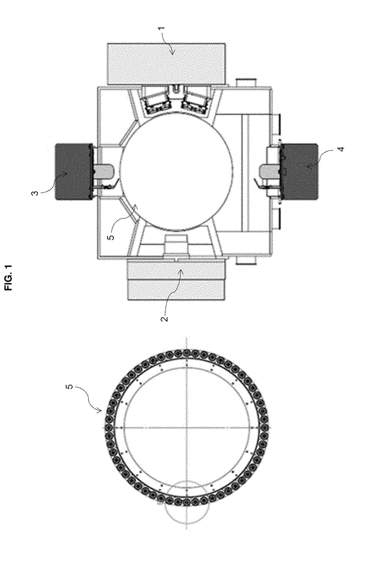
[0120]A heat receiver tube loaded in a rotating carousel drum was introduced as substrate in the attaching chamber containing a DC sputtering equipped with an aluminum cathode positioned in front of the substrate at a distance of about 8 mm.

[0121]Argon flow of 1000 sccm was introduced using flow controllers. The argon flow was adjusted to maintain an equilibrium pressure with the pumping velocity. The working pressure in the attaching chamber (about 2.0×10⁻³-3.0×10⁻³ mBar) was measured by means of an Ion Gauge. An Al layer was deposited on the substrate in the attaching chamber applying 18 kW power.

[0122]The coated substrate was then transferred to the transforming chamber containing a Dual MF Sputtering having two aluminum cathodes wherein a power of 10 kW was applied and an oxygen flow of 400-800 sccm was introduced. The metal was thus oxidized by the presence of oxygen to produce Al2O3 at a rat...

example 2

ic Layer)

[0125]A functional layer of SiO2 was prepared by the method of the invention.

[0126]A heat receiver tube loaded in a rotating carousel drum was introduced as substrate in the attaching chamber containing a DC sputtering equipped with a silicon cathode positioned in front of the substrate at a distance of about 8 mm.

[0127]Argon flow of 1000 sccm was introduced using flow controllers. The argon flow was adjusted to maintain an equilibrium pressure with the pumping velocity. The working pressure in the attaching chamber (about 2.0×10⁻³-3.0×10⁻³ mBar) was measured by means of an Ion Gauge. A Si layer was deposited on the substrate in the deposition chamber applying a power of 28 kW.

[0128]The coated substrate was then transferred to the transforming chamber containing a Dual MF Sputtering having one or two Silicon cathodes wherein a power of 10-60 kW was applied and an oxygen flow of 400-800 sccm was introduced. The metal was thus oxidized by the presence of oxygen to produce SiO...

example 3

ike Layer)

[0131]A functional layer of (ZrB2 / AlN)r was prepared by the method of the invention.

[0132]A heat receiver tube loaded in a rotating carousel drum was introduced as substrate in the attaching chamber containing a DC sputtering equipped with a ZrB2 cathode and an aluminum cathode positioned in front of the substrate at a distance of about 8 mm.

[0133]Argon flow of 1000 sccm was introduced using flow controllers. The argon flow was adjusted to maintain an equilibrium pressure with the pumping velocity. The working pressure in the attaching chamber (about 2.0×10⁻³-3.0×10⁻³ mBar) was measured by means of an Ion Gauge. A ZrB2 layer and an Al layer were deposited on the substrate in the deposition chamber.

[0134]The coated substrate was then transferred to the transforming chamber containing a Dual MF Sputtering having one or two aluminum cathodes wherein a power of 5-60 kW was applied (the power level was varied in order to obtain different coatings) and a nitrogen flow of 200-800...


PUM

PropertyMeasurementUnit
Dielectric polarization enthalpyaaaaaaaaaa
Electrical conductoraaaaaaaaaa
Vacuumaaaaaaaaaa

Abstract

A method for arranging at least one functional layer suitable for a multilayer solar selective coating is disclosed in the present application. Particularly, the method provided allows depositing arrangements of conductive and dielectric layers as well as coatings of dielectrics onto a substrate. The method disclosed may be used to prepare functional coatings with optical properties such as absorbing layers, anti-reflective layers and diffusion barriers.

Description

FIELD OF THE INVENTION[0001]This invention relates to a method for arranging (i.e. depositing) at least one functional layer suitable for a multilayer solar selective coating. In particular, the method disclosed may be used to prepare functional coatings based on dielectric materials or on an arrangement of dielectric and conductive layers.[0002]The functional coatings can be applied in the field of solar concentration technology for producing electric power from solar radiation, and more particularly, to heat receiver tubes in parabolic-trough power plants.BACKGROUND OF THE INVENTION[0003]A sun energy collecting unit of a sun field power plant based on the concentrated solar power technique comprises, for instance, a trough with parabolic mirrors and a heat receiver tube. The heat receiver tube (also commonly known as heat collector element (HCE)) is arranged in a focal line of the mirrors. The sunlight is focused by the mirrors to the heat receiver tube, which is filled with a hea...

Claims


Application Information

Patent Timeline
IPC IPC(8): C23C14/34C23C14/06C23C14/08F24S70/25F24S20/20F24S70/30
CPCC23C14/3464C23C14/0688C23C14/081F24S70/25F24S20/20F24S70/30F24S70/16C23C14/10F24S70/225Y02E10/40
Inventor BARKAI, MENASHE
Owner RIOGLASS SOLAR SCH SL
Why Eureka
Try Eureka