System and method for enhanced data analysis with video enabled software tools for medical environments

a software tool and enhanced data technology, applied in the field of medical software tools, can solve the problems of reducing healthcare costs and postoperative complications, and achieve the effect of facilitating equipment integration

Active Publication Date: 2018-11-29
WADE JACK
View PDF12 Cites 21 Cited by
  • Summary
  • Abstract
  • Description
  • Claims
  • Application Information

AI Technical Summary

Benefits of technology

[0006]Various embodiments of the disclosed technology provide a medical software tools platform that utilizes a surgical display to provide access to medical software tools, such as medically-oriented applications or widgets, that can assist those in the operating room, such as a surgeon and their surgical team, with a surgery. For various embodiments, the medical software tools platform and its associated medical software tools are presented on a surgical display (e.g., being utilized in an operating room) over an image stream provided by a surgical camera (e.g., in use in the operating room) or other medical device that generates image streams. An image stream can include video or a series of static images (e.g., medical ultrasound device). Various medical software tools can provide features and functions that can facilitate integration of equipment in an operating room or add medical context awareness to anatomic structures presented in the image stream from the surgical camera.

Problems solved by technology

Moreover, various desktop tools may assist surgeons in making critical decisions in the operating room, which can potentially reduce rates of postoperative complications and decrease healthcare costs.

Method used


Image

  • System and method for enhanced data analysis with video enabled software tools for medical environments
  • System and method for enhanced data analysis with video enabled software tools for medical environments
  • System and method for enhanced data analysis with video enabled software tools for medical environments

Examples


Embodiment Construction

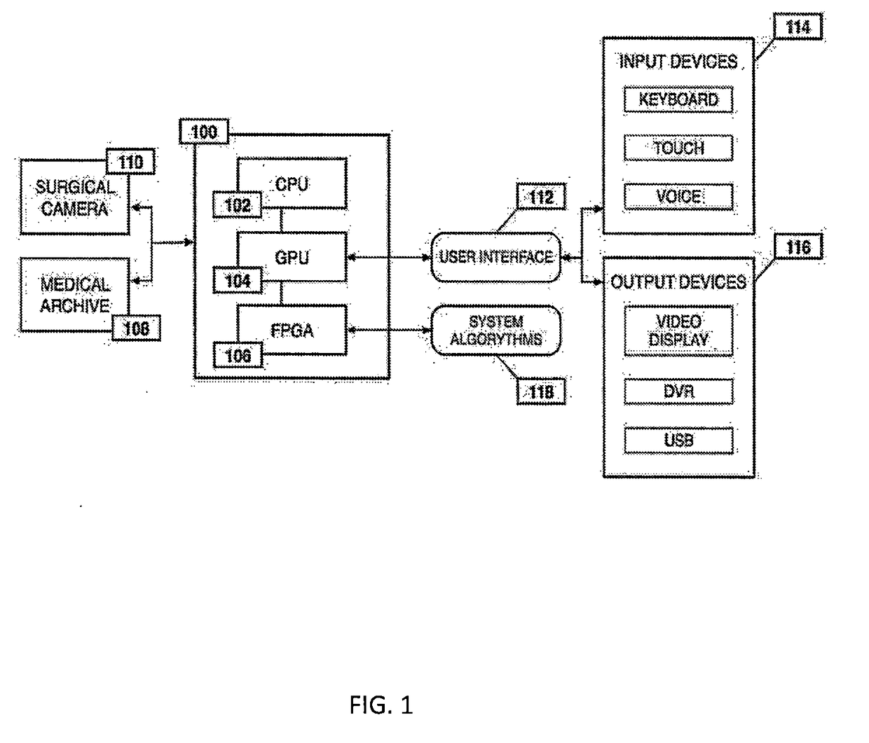
[0026]FIG. 1 is a block diagram illustrating an example of the overall processing system that may be used in implementing various features of embodiments of the disclosed technology. In accordance with the preferred embodiment of the present invention, the processing system 100 consists of processor elements such as: a central processing unit (CPU) 102; a graphics processing unit (GPU) 104; and a field programmable gate array (FPGA) 106. The processing system 100 may be used to retrieve and process raw data derived from a surgical camera 110 or a data storage device, such as a medical archive 108. The surgical camera 110 or medical archive 108 transmits a data stream to the processing system 100, whereby that data is processed by the CPU 102. The FPGA 106, connected to the CPU 102 and the GPU 104, simultaneously processes the received data by using a series of programmed system algorithms 118, thus functioning as an image clarifier within the processing system 100. The GPU 104 commu...


PUM


Abstract

Medical software tools platform utilizes a surgical display to provide access to specific medical software tools, such as medically-oriented applications or tools, that can assist those in the operating room, such as a surgeon or surgical team, with a surgery. In particular, an optical sensor located within an endoscopic camera may register subtle differences in color characteristics reflected from a tissue surface and in turn transmit the information to a medical image processing system. Moreover, the new tools are intended to help surgeons better determine the boundaries between healthy and diseased regions during surgical procedures. Various tools are intended to be used in procedures where indocyanine green (ICG) fluorescent dye is used. Intraoperative fluorescence imaging is commonly used during minimally invasive procedures to enable surgeons to visualize tissue perfusion and anatomical structures. The term perfusion refers to the passage of blood and tissue fluid through the capillary bed. Intraoperative fluorescence imaging can also be used to improve visualization of vessels and structures, which, in turn, may reduce the risk of complications during minimally invasive surgeries.

Description

PRIORITY CLAIM[0001]This application, a continuation in part, claims the benefit of U.S. patent application Ser. No. 15 / 789,948, filed Oct. 20, 2017, which is a continuation in part of U.S. patent application Ser. No. 15 / 652,031, filed Jul. 17, 2017, which is a continuation in part of U.S. patent application Ser. No. 15 / 456,458, filed Mar. 10 2017, which is a continuation in part of U.S. patent application Ser. No. 15 / 377,817, filed Dec. 13, 2016, which is a continuation of U.S. patent application Ser. No. 14 / 107,329, filed Dec. 16, 2013, and issued as U.S. Pat. No. 9,526,586 on Dec. 27, 2016, which claims the benefit of U.S. Provisional Patent Application Ser. No. 61 / 865,037, filed Aug. 12, 2013. This application also claims the benefit of and is a continuation in part of U.S. patent application Ser. No. 15 / 170,575, filed Jun. 1, 2016, which claims the benefit of Ser. No. 13 / 430,489, filed Mar. 26, 2012, which is a continuation-in-part of U.S. patent application Ser. No. 12 / 776,048...

Claims


Application Information

Patent Timeline
Patent Type & Authority Applications(United States)
IPC IPC(8): A61B34/00A61B1/00A61B1/313A61B90/00
CPCA61B90/361A61B1/00009A61B1/3132G06T2207/30004G06T2200/24A61B34/25A61B1/0005A61B1/043A61B2034/256G16H30/40G16H40/63G16H10/60G16H50/70G16H20/40G16H20/17A61B1/000095
Inventor WADE, JACK
Owner WADE JACK
Why Eureka
Try Eureka