
Wavelength tunable optical sources, filters and detectors

Active Publication Date: 2018-12-06
VALORBEC PARTNERSHIP
View PDF0 Cites 9 Cited by
  • Summary
  • Abstract
  • Description
  • Claims
  • Application Information

AI Technical Summary

Benefits of technology

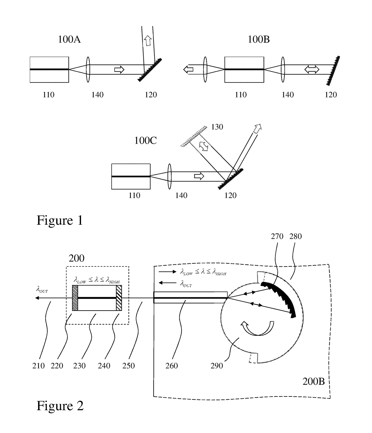
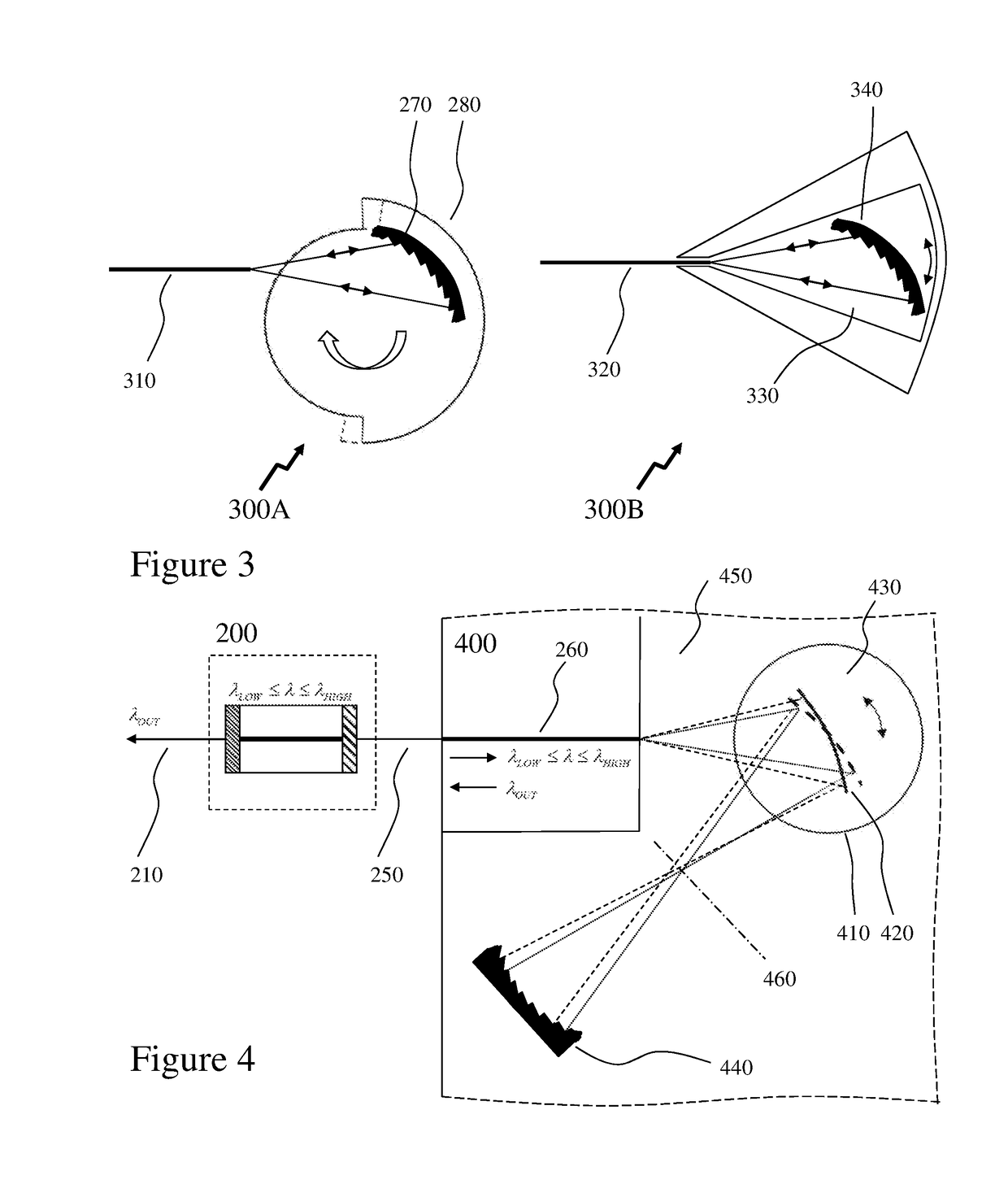
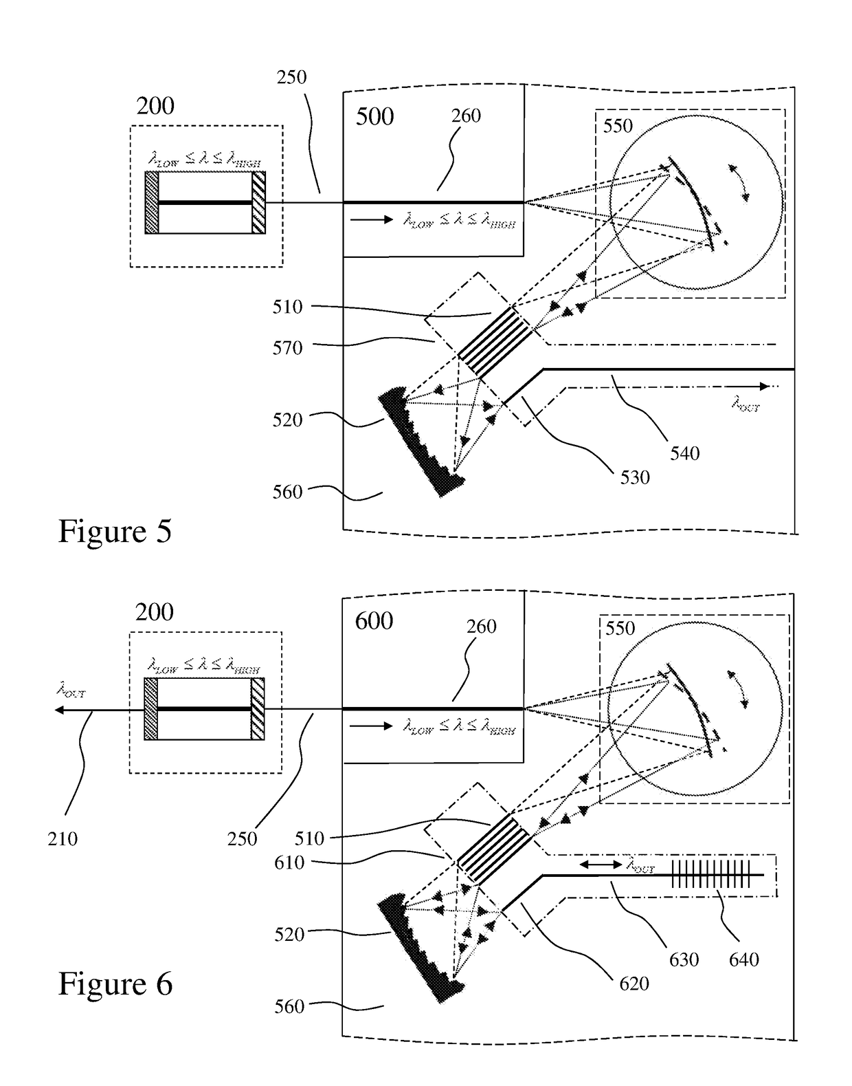
The present invention aims to overcome limitations in the prior art related to microoptoelectromechanical systems (MOEMS) and optical microelectromechanical systems (MEMS) based wavelength tunable components. The invention provides a photonic circuit that includes a substrate, a rotatable microelectromechanical systems (R-MEMS) element with a planar waveguide, and a channel waveguide supporting optical signals within a predetermined wavelength range. The rotation of the R-MEMS results in optical signals within a predetermined subset of the predetermined wavelength range being coupled back to the channel waveguide. The invention also provides a photonic circuit with a reflective diffraction grating and a plurality of filter waveguides for coupling optical signals from the R-MEMS to another channel waveguide. The invention further provides a photonic circuit with a concave diffraction grating for retro-reflecting optical signals coupled into the planar waveguide from the rib waveguide back to the rib waveguide. The technical effects of the invention include improved coupling of optical signals, reduced signal loss, and improved wavelength tuning.

Problems solved by technology

However, within the prior art the majority of MEMS and MOEMS devices were designed for free space optical interconnections.

Method used


Image

  • Wavelength tunable optical sources, filters and detectors
  • Wavelength tunable optical sources, filters and detectors
  • Wavelength tunable optical sources, filters and detectors

Examples


Embodiment Construction

[0038]The present invention is directed to microoptoelectromechanical systems (MOEMS) and more particular to designs for optical microelectromechanical systems (MEMS) based wavelength tunable components such as sources, filters, and detectors exploiting such optical MEMS elements.

[0039]The ensuing description provides representative embodiment(s) only, and is not intended to limit the scope, applicability or configuration of the disclosure. Rather, the ensuing description of the embodiment(s) will provide those skilled in the art with an enabling description for implementing an embodiment or embodiments of the invention. It being understood that various changes can be made in the function and arrangement of elements without departing from the spirit and scope as set forth in the appended claims. Accordingly, an embodiment is an example or implementation of the inventions and not the sole implementation. Various appearances of “one embodiment,”“an embodiment” or “some embodiments” do...


PUM


Abstract

Wavelength division multiplexing (WDM) has enabled telecommunication service providers to fully exploit the transmission capacity of optical fibers. State of the art systems in long-haul networks now have aggregated capacities of terabits per second. Moreover, by providing multiple independent multi-gigabit channels, WDM technologies offer service providers with a straight forward way to build networks and expand networks to support multiple clients with different requirements. In order to reduce costs, enhance network flexibility, reduce spares, and provide re-configurability many service providers have migrated away from fixed wavelength transmitters, receivers, and transceivers, to wavelength tunable transmitters, receivers, and transceivers as well as wavelength dependent add-drop multiplexer, space switches etc. However, to meet the competing demands for improved performance, increased integration, reduced footprint, reduced power consumption, increased flexibility, re-configurability, and lower cost it is desirable to exploit / adopt monolithic optical circuit technologies, hybrid optoelectronic integration, and microelectromechanical systems (MEMS).

Description

CROSS-REFERENCE TO RELATED APPLICATIONS[0001]This patent application claims the benefit of priority as a 371 National Phase entry application from PCT / CA2016 / 000,295 filed on Dec. 1, 2016 entitled “Wavelength Tunable Optical Sources, Filters and Detectors”, which itself claims the benefit of priority from U.S. Provisional Patent Application 62 / 261,396 filed on Dec. 1, 2015 entitled “Wavelength Tunable Optical Sources, Filters and Detectors” the entire contents of each being incorporated herein by reference.FIELD OF THE INVENTION[0002]This invention relates to microoptoelectromechanical systems (MOEMS) and more particular to designs for optical microelectromechanical systems (MEMS) based wavelength tunable components such as sources, filters, and detectors exploiting such optical MEMS elements.BACKGROUND OF THE INVENTION[0003]Dense wavelength division multiplexing (DWDM) and coarse wavelength division multiplexing (CWDM) have enabled telecommunication service providers to fully explo...

Claims


Application Information

Patent Timeline
Patent Type & Authority Applications(United States)
IPC IPC(8): G02B26/08B81B7/02B81B5/00G02B6/124H04J14/02
CPCG02B26/0841B81B7/02B81B5/00G02B6/124H04J14/0215G02B6/3534
Inventor PACKIRISAMY, MUTHUKUMARANPOTTIER, PIERRE
Owner VALORBEC PARTNERSHIP
Learn More