Electrodialysis systems and methods for desalination

Active Publication Date: 2018-12-20
MASSACHUSETTS INST OF TECH
View PDF0 Cites 3 Cited by
  • Summary
  • Abstract
  • Description
  • Claims
  • Application Information

AI Technical Summary

Benefits of technology

[0075]FIG. 25 is a graph of current density (A/m2) as a function of diluate concentration for a product concentration of 100 mg/L and 200 mg/L. The dashed lines show the current density as a function of diluate concentration for

Problems solved by technology

However, these systems are inefficient, recovering only 25-40% [2] of the feed, and thereby stressing limited groundwater resources.
While ED appears to be a promising alternative for domestic groundwater desalination, limited work has been performed to characterize the design of a system that is appro

Method used


Image

  • Electrodialysis systems and methods for desalination
  • Electrodialysis systems and methods for desalination
  • Electrodialysis systems and methods for desalination

Examples


Example

Example 1

Optimal Design of a Batch Electrodialysis System for Domestic Desalination

[0141]In this work, we used simulation to investigate how a domestic batch ED system could be designed to minimize cost while providing production rates and product water concentrations that are suitable for domestic use. In particular, we aimed to address the following:[0142]1. How should a domestic ED system be configured to minimize cost?[0143]2. How do production rate and concentration requirements affect the design?[0144]3. What are the primary contributors to the cost?

II. System Description

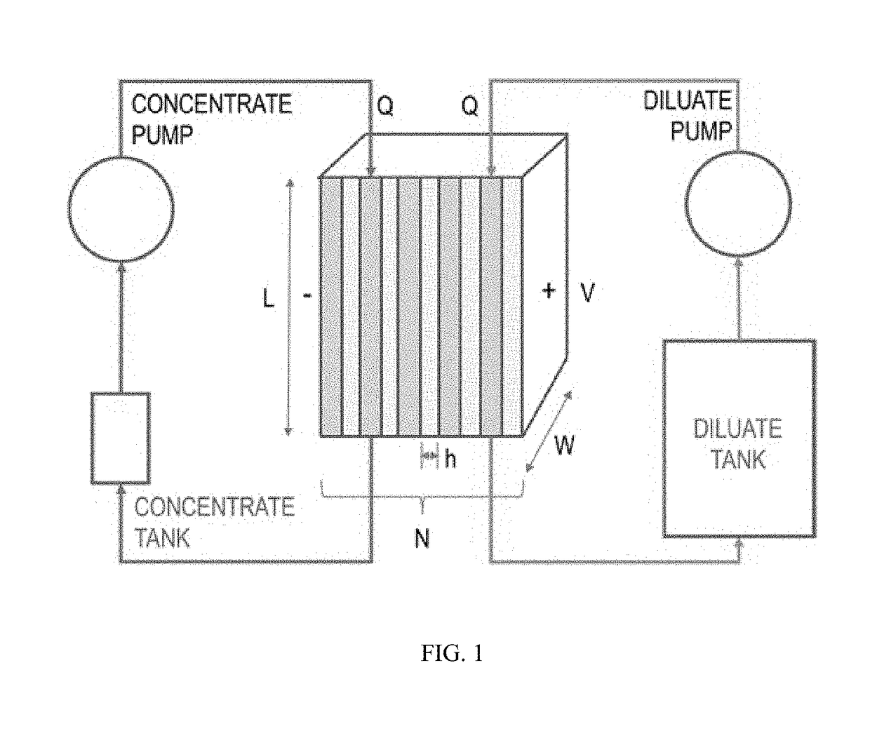
[0145]The batch ED system (FIG. 1) proposed by Nayar et al. [7] and analyzed here consists of two primary flow circuits: one for the diluate, and the other for the concentrate. At the start of each batch process, both tanks hold feedwater at the same concentration. The relative volume of water in the diluate versus the concentrate circuits governs the recovery ratio of the process. During desalination, a volta...

Example

EXAMPLE 2

Cost-Optimal Design of a Batch Electrodialysis System For Domestic Desalination of Brackish Groundwater

[0214]This study presents the pareto-optimal design of a domestic point-of-use batch electrodialysis (ED) system. Specifically, the optimal geometry, flow-rates, and applied voltage for total cost minimization were explored for varying production rate (9-15 L / hr) and product concentration (100-300 mg / L) requirements, while feed concentration and recovery ratio were maintained at 2000 mg / L and 90%, respectively. Capital cost dominated over energetic cost; hence, optimal designs maximized current density. Capital cost was significantly higher for 100 mg / L systems, than 200 and 300 mg / L: $141 vs. $93 and $79, at 12±0.5 L / hr of production. Pumps were an important consideration, contributing up to 46% of the total cost. Large membrane length-to-width aspect ratios (3.5:1 to 6:1) and thin channels (0.30-0.33 mm) promoted high current densities, and 11-21 cm / s velocities optimize...

Example

EXAMPLE 3

Increasing the Speed of Brackish Water Batch Electrodialysis Desalination Using Open-Loop Voltage Control

[0358]Several studies have been performed on the design and optimization of batch ED systems for brackish water desalination. Most authors suggest operating at high current densities i to reduce the membrane area required for a given salt removal rate. Since the capital cost CC scales with the membrane area requirement,

CC˜1 / i.

Therefore, the capital cost of the system can be decreased by increasing current density. However, few have suggested controlling the voltage control to maximize the current density as a function of diluate concentration. As a result, controller descriptions and experimental comparisons with standard operation are lacking. We speculate that at least for large-scale systems, this solution is often neglected because:[0359]Cost and difficulty of implementation when dealing with high power.[0360]Industrial operations are often more concerned about the e...


PUM


Abstract

Described are improved electrodialysis (ED) desalination systems and methods comprising voltage regulation and/or improved stack geometries. The systems and methods provide product water concentrations suitable for drinking (having a total dissolved solids concentration of less than 500 mg/L or 500 ppm) and have a high product recovery ratio.

Description

RELATED APPLICATION[0001]This application claims the benefit of U.S. Provisional Application No. 62 / 504,628 filed May 11, 2017. The entire contents of the above application are incorporated herein by reference herein.BACKGROUND OF THE INVENTION[0002]Indian homes currently rely on domestic reverse osmosis (RO) systems to desalinate groundwater to a salt content with total dissolved solids (TDS) that is suitable for drinking (less than 500 mg / L [1]). However, these systems are inefficient, recovering only 25-40% [2] of the feed, and thereby stressing limited groundwater resources. Given that the concentration of the groundwater underlying a majority of India is under 2000 mg / L, electrodialysis (ED) can provide a higher recovery and more energy-efficient desalination compared to RO [3,4].[0003]While ED appears to be a promising alternative for domestic groundwater desalination, limited work has been performed to characterize the design of a system that is appropriate for the given appl...

Claims


Application Information

Patent Timeline
IPC IPC(8): C02F1/469B01D61/46B01D61/54C02F1/00
CPCC02F1/4693B01D61/46B01D61/54C02F1/008B01D2311/243C02F2103/08C02F2201/46C02F2209/05C02F2301/046B01D2311/25C02F2303/04B01D2311/2649C02F1/001C02F1/283C02F1/32C02F1/4604C02F2103/06C02F2201/46115C02F2201/46135C02F2209/001C02F2209/006C02F2209/10C02F2209/40Y02A20/124
Inventor SHAH, SAHIL RAJESHWINTER, V, AMOS G.WRIGHT, NATASHA C.
Owner MASSACHUSETTS INST OF TECH
Why Eureka
Try Eureka