Cardiac valve prosthesis

a prosthetic device and cardiac valve technology, applied in the field of implantable prosthetic devices, can solve the problems of inability to fully function, and inability to fully function, and achieve the effect of reducing the capacity of filler materials, effective fluid tightness, and increasing circumferential exten

Active Publication Date: 2018-12-27
INNOVHEART SRL
View PDF0 Cites 0 Cited by
  • Summary
  • Abstract
  • Description
  • Claims
  • Application Information

AI Technical Summary

Benefits of technology

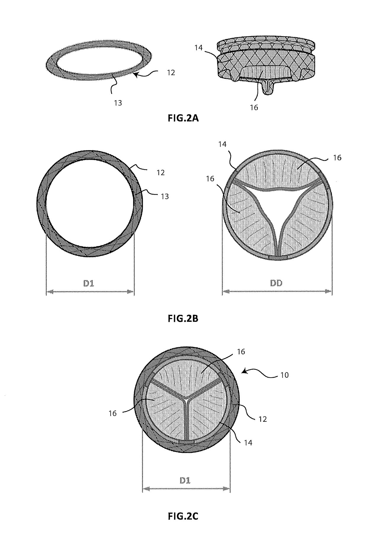
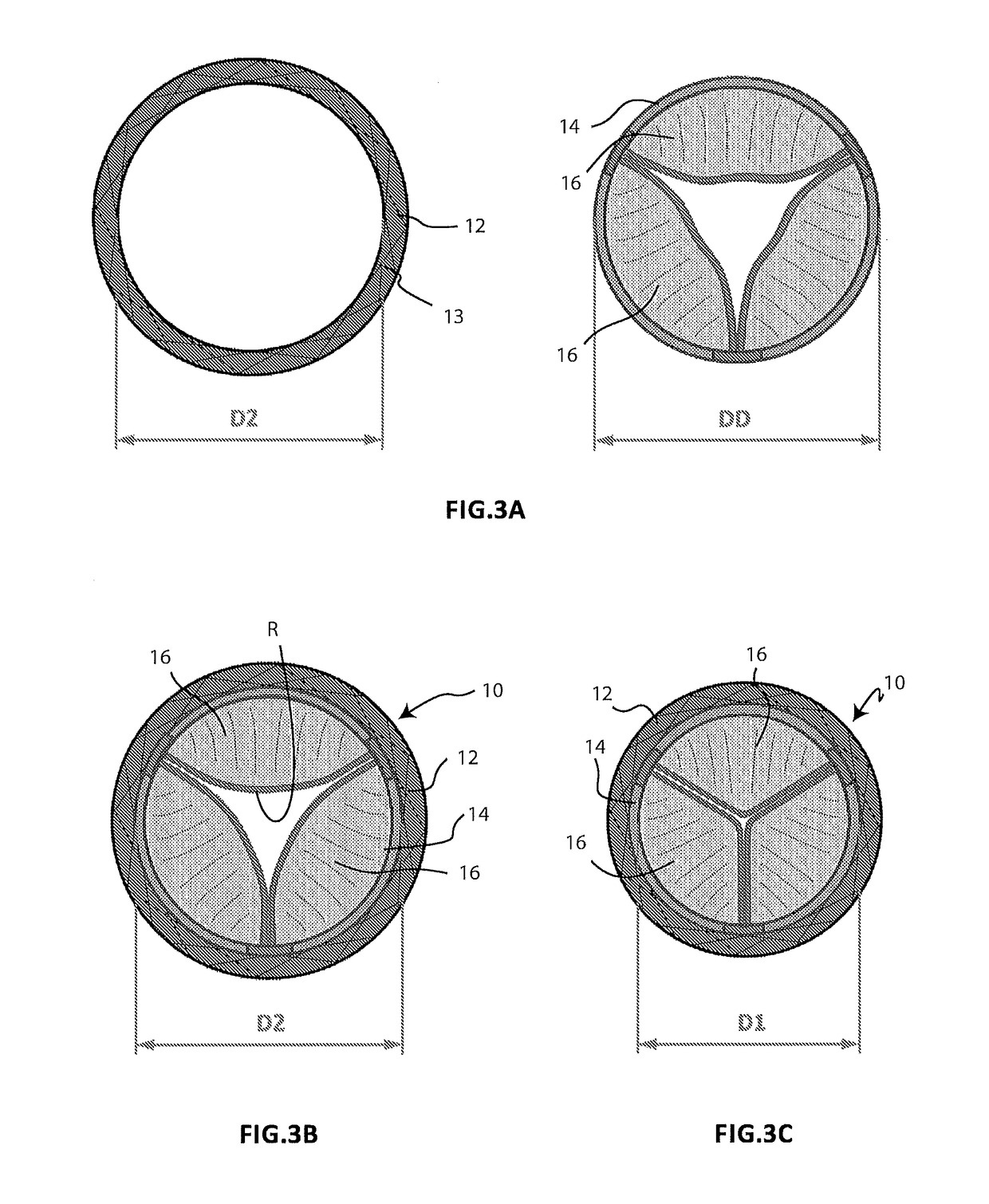
[0031]More specifically, a solution in accordance with an embodiment of the invention is compatible with a prosthetic system which comprises an annular element which is capable of being positioned at the rear of the leaflets of the native intra-ventricular valve, so as to surround it completely, and a central valve member which is collapsible to a diameter which is substantially less than that of the implant and which is capable of expanding inside the mitral opening. This solution makes provision for the annular element which is part of the prosthetic system to include a core which is generally but not necessarily produced from metal material which has in toto or even only partially a meshed form, or a helical form, or any geometry which allows the resilient deformation thereof both in extension, that is to say, in the longitudinal direction (obtaining the increase of the axial extent of the annular element, that is to say, the overall length), and with respect to the plane in which the annular element is located, that is to say, in a transverse direction (obtaining the variation of shape of the annular element). During the construction step of the component, the structure is deformed in accordance with degrees of freedom which are allowed by the configuration thereof and in any case not beyond the resilience limit of the material from which it is composed, in order to ensure the resilient return thereof to the natural configuration once the constraint which maintains it in the deformed configuration is removed. By way of example, the annular element may be deformed by increasing the axial extent thereof or by imposing an ovalized geometry or in any case a geometry which is different from the one expected during the normal operation condition, or by applying the two deformations at the same time. An annular element modified in this manner achieves the double result both of making the prosthetic system suitable for the implantation in a native annulus having greater dimensions, as a result of the increased circumferential extent and therefore the equivalent diameter of the annular element, and of bringing about the intra-prosthetic insufficiency in the implanted device. With regard to this last point, it may be observed that the central member of the prosthetic system, which element supports the prosthetic leaflets, is preferably constituted by a collapsible and expansible frame, the expanded formation of which, once the prosthesis is implanted, is limited by the geometry, the dimensions and the resilient characteristics of the annular element which completely surrounds it. In fact, during the implantation method, the central member expands until it is mechanically connected to the annular element. The final configuration of the prosthesis is therefore determined by the result of the balance between the radial force applied by the central member, the expansion of which remains limited and incomplete in any case, and the constraint constituted by the annular element. The prosthetic leaflets which are supported by the central member have dimensions adapted to provide optimum coaptation and therefore eff...

Problems solved by technology

Insufficiency of a cardiac valve is a malfunction which is hugely incapacitating for the patient and very onerous for the cardiac muscle.
Insufficiency is a particularly serious malfunction for an atrio-ventricular valve, specifically for the mitral valve.
That malfunction often triggers a vicious circle which leads to a rapid deterioration of the pathological outlook.
In fact, blood regurgitation through the mitral valve inhibits the efficiency of the left ventricle, reducing the volume of oxygenated blood which is effectively discharged by the heart towards the peripheral chambers for the same volumetric systolic contraction of the ventricle itself.
However, the dilation of the ventricular chamber also results in a dilation of the annulus of the mitral valve, in addition to a deformation, and therefore malfunctioning, of the sub-valvular apparatus thereof, which tends to aggravate the lack of competence of the mitral valve itself, thereby increasing the regurgitated proportion and further reducing the pumping efficiency of the ventricle.
Therefore, it is evident how the attempt to compensate for the mitral regurgitation via a dilation of the ventricle results in an increase of the regurgitation itself and therefore a triggering of a vicious circle which rapidly leads to the occurrence of cardiac insufficiency (heart failure).
This outlook is further aggravated by the fact that the increase in the volume of the ventricle for diastolic purposes and the simultaneous thinning of the ventricle wall increases significantly the level of stress undergone by the cardiac muscle during the systolic phase (so-called afterload), quickly generating a state of suffering and weakening of the myocardium which contributes to the deterioration of the condition of cardiac insuffic...

Method used


Image

  • Cardiac valve prosthesis
  • Cardiac valve prosthesis
  • Cardiac valve prosthesis

Examples


Embodiment Construction

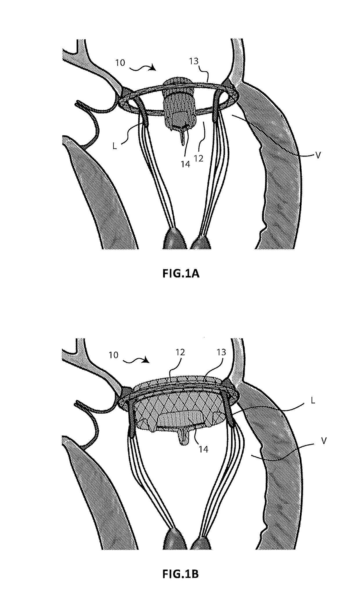
[0053]FIGS. 1A and 1B schematically illustrate two different steps of the implantation method of a prosthesis 10 for a cardiac valve according to the present invention, which prosthesis is used to replace the functionality of a native atrio-ventricular valve V to be treated. The prosthesis 10 comprises a first component in the form of an annular element 12 and a second component in the form of a central member 14, which supports prosthetic valve leaflets 16. During the implantation method, the annular element 12 is positioned outside the native atrio-ventricular valve V in order to completely surround it, while the central member 14 is expanded inside the same native atrio-ventricular valve V (FIG. 1A). The expansion of the central member 14 causes the two components 12, 14 to be connected to each other (FIG. 1B). The contact between the two components 12, 14 is not direct but instead occurs with the interposition of the leaflets L of the native valve V which remain interpolated bet...


PUM

PropertyMeasurementUnit
Forceaaaaaaaaaa
Deformation enthalpyaaaaaaaaaa
Biodegradabilityaaaaaaaaaa

Abstract

A prosthesis for a cardiac valve including prosthetic leaflets which are intended to functionally replace the native leaflets of a cardiac valve following the implantation of the cardiac prosthesis. The prosthesis also including a prosthetic member on which there are mounted the prosthetic leaflets and which is intended to take up a stable, predetermined functional configuration in which the prosthetic member and the prosthetic leaflets reproduce the functionally correct configuration for the purpose of the physiological replacement of the native cardiac valve. The prosthetic member is preconfigured so as to move gradually from an altered, temporary functional configuration, in which the prosthetic member has a deformed geometry with respect to the stable, predetermined stable functional configuration, to said stable, predetermined functional configuration.

Description

FIELD OF APPLICATION[0001]The present invention relates to the field of implantable prosthetic devices for the treatment of malfunctions of cardiac valves.[0002]The invention has been developed with particular regard to an implantable prosthetic device which is capable of replacing the physiological function of a malfunctioning cardiac valve.TECHNOLOGICAL BACKGROUND[0003]Cardiac valves are organs which preside over the correct functioning of the heart as a pump for the generation of blood flow in the circulation system of living beings. The main objective thereof involves making the blood flow unidirectional inside the cardiac cavities, being essential both in the filling phase of the cavities, known as the diastolic phase, and in the blood discharge phase, known as the systolic phase.[0004]There are four cardiac valves which are present in the human heart. The most critical, that is to say, those whose malfunction is mainly evident as a risk of premature death or significant degrad...

Claims


Application Information

Patent Timeline
IPC IPC(8): A61F2/24
CPCA61F2/2418A61F2210/0004A61F2220/0025A61F2250/001A61F2250/0063A61F2/2412A61L27/58A61L2430/20
Inventor RIGHINI, GIOVANNI
Owner INNOVHEART SRL
Why Eureka
Try Eureka