
Nanoparticles and systems and methods for synthesizing nanoparticles through thermal shock

a nanoparticle and thermal shock technology, applied in the field of nanoparticles, can solve the problems of radically changing the morphology of the end product, challenging to synthesize uniform small-size nanoparticles, and challenging to uniformly disperse nanoparticles on a substra

Active Publication Date: 2018-12-27
UNIV OF MARYLAND
View PDF0 Cites 17 Cited by
  • Summary
  • Abstract
  • Description
  • Claims
  • Application Information

AI Technical Summary

Benefits of technology

This patent describes methods, systems, and composites for synthesizing nanoparticles on a substrate. This involves depositing micro-sized particles or salt precursors onto a substrate, and then subjecting the substrate and particles to a rapid, high temperature thermal shock to cause the particles to self-assemble into nanoparticles on the substrate. The technical effects of this patent are the ability to produce nanoparticles on a substrate with improved control over size, shape, and distribution, thereby expanding the range of applications for nanoparticle technology.

Problems solved by technology

This makes it challenging to synthesize uniform small-size nanoparticles.
Moreover, uniformly dispersing nanoparticles on a substrate is even more challenging.
Slight differences in reaction conditions can drastically change the morphology of the end product, which may be detrimental to the performance of the catalyst.
This problem may become more severe and relevant when the catalyst has dimensions on the nanoscale level.

Method used


Image

  • Nanoparticles and systems and methods for synthesizing nanoparticles through thermal shock
  • Nanoparticles and systems and methods for synthesizing nanoparticles through thermal shock
  • Nanoparticles and systems and methods for synthesizing nanoparticles through thermal shock

Examples


Embodiment Construction

[0025]Embodiments of the systems and methods of synthesizing nanoparticles on substrates are described in detail with reference to the drawings, in which like or corresponding reference numerals designate identical or corresponding elements in each of the several views.

[0026]This disclosure relates to low cost, simple, ultra-fast synthesis of nanoparticles for nanocatalysis, which is beneficial for the development of high performance nanocatalysts used for energy conversion and electrochemical processes, such as water splitting, fuel cells, metal air batteries, and other catalytic reactions, such as biomass conversion, ammonia oxidation, and so on.

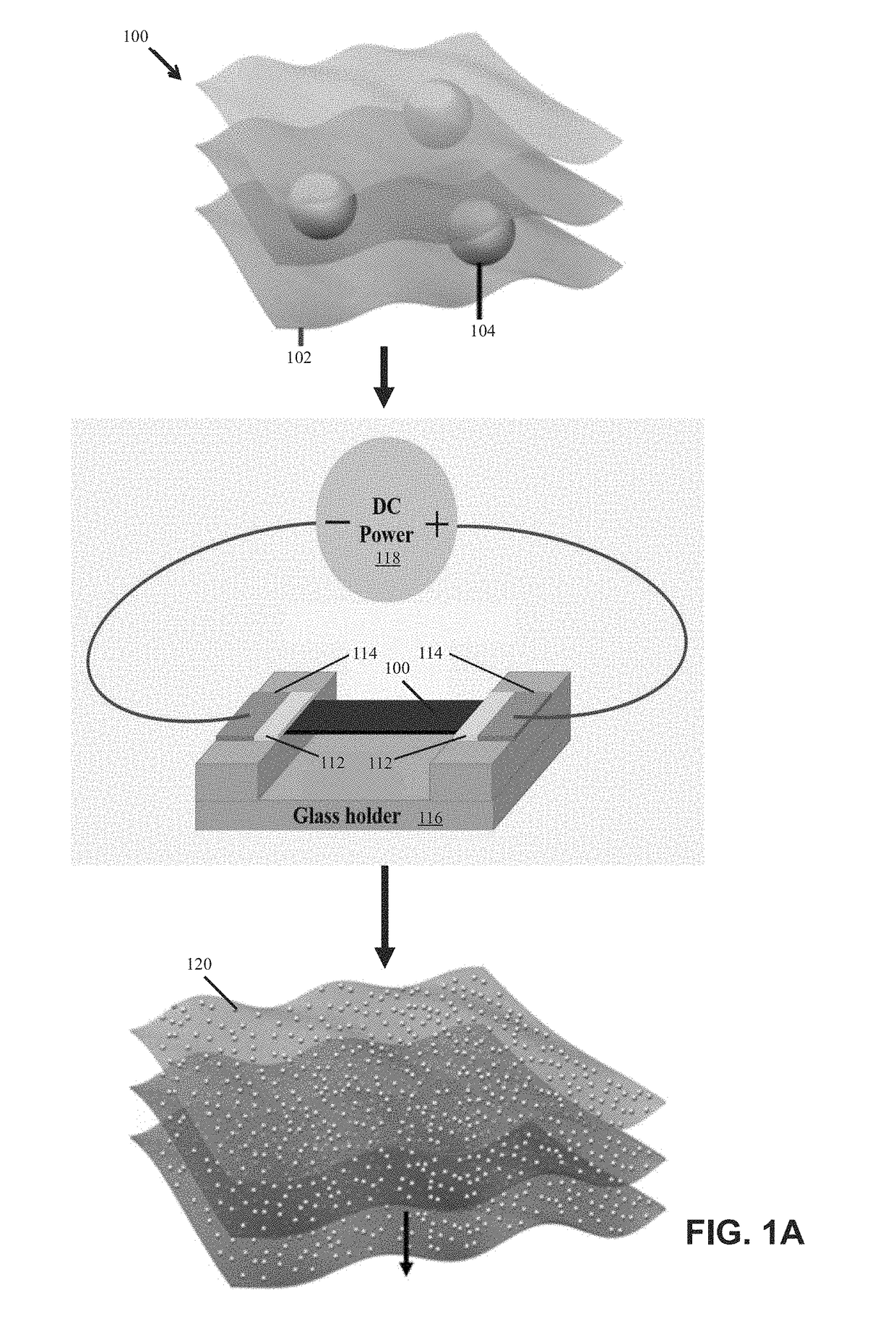
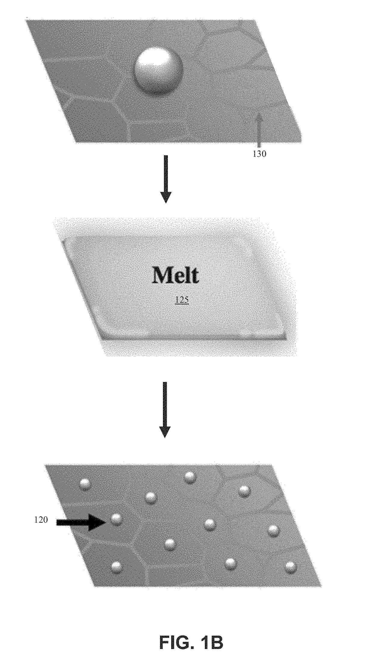
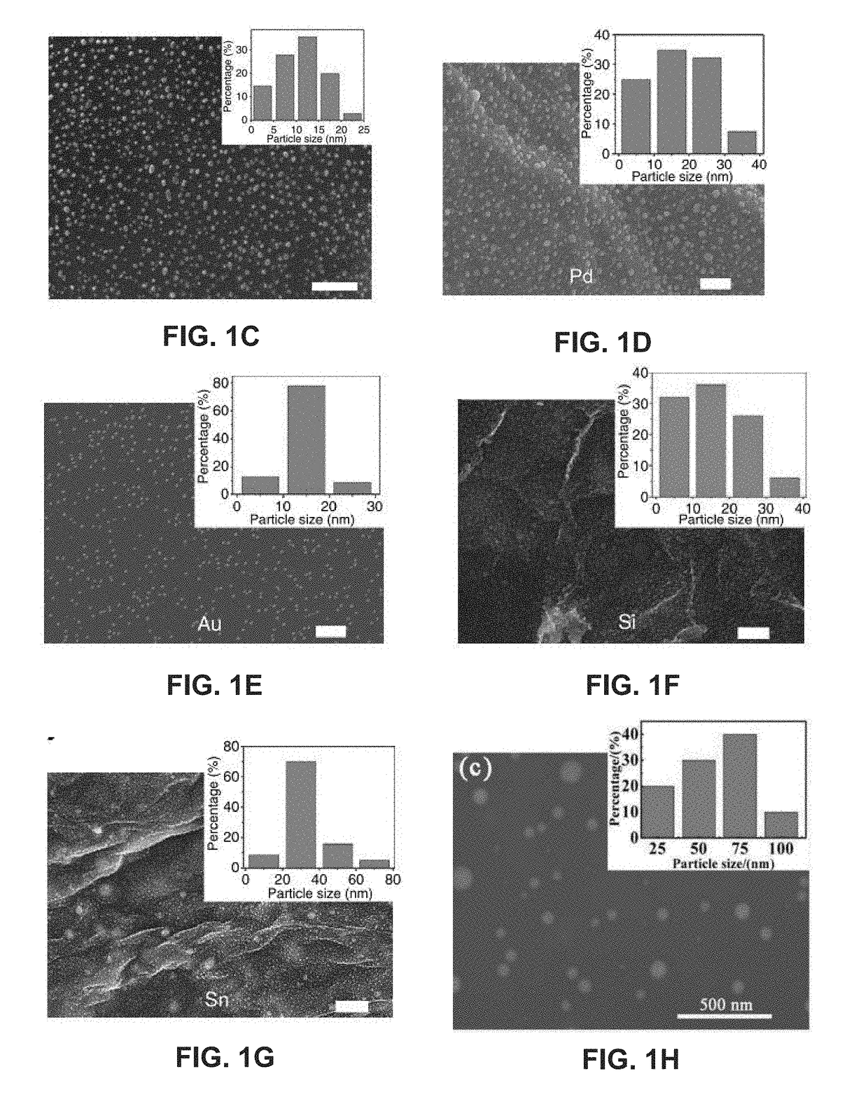
[0027]FIG. 1A illustrates an example method for constructing nanoparticles (e.g., metallic or semiconductor nanoparticles) on a substrate (e.g., reduced graphene oxide (RGO)) from micro-sized particles. The micro-sized particlesin the substrate are self-assembled into nanoparticles when heated by direct Joule heating. The micro-sized parti...


PUM

PropertyMeasurementUnit
Temperatureaaaaaaaaaa
Diameteraaaaaaaaaa

Abstract

Systems and methods of synthesizing nanoparticles on substrates using rapid, high temperature thermal shock. A method involves depositing micro-sized particles or salt precursors on a substrate, and applying a rapid, high temperature thermal pulse or shock to the micro-sized particles or the salt precursors and the substrate to cause the micro-sized particles or the salt precursors to become nanoparticles on the substrate. A system may include a rotatable member that receives a roll of a substrate sheet having micro-sized particles or salt precursors; a motor that rotates the rotatable member so as to unroll consecutive portions of the substrate sheet from the roll; and a thermal energy source that applies a short, high temperature thermal shock to consecutive portions of the substrate sheet that are unrolled from the roll by rotating the first rotatable member. Some systems and methods produce nanoparticles on existing substrate. The nanoparticles may be metallic, ceramic, inorganic, semiconductor, or compound nanoparticles. The substrate may be a carbon-based substrate, a conducting substrate, or a non-conducting substrate. The high temperature thermal shock process may be enabled by electrical Joule heating, microwave heating, thermal radiative heating, plasma heating, or laser heating.

Description

CROSS-REFERENCE TO RELATED APPLICATIONS[0001]This application claims the benefit of and priority to U.S. Provisional Application No. 62 / 523,646, filed on Jun. 22, 2017, the entire contents of which are incorporated herein by reference.BACKGROUNDTechnical Field[0002]This disclosure relates to nanoparticles synthesized or constructed on a substrate of interest through thermal shock, their methods of construction, and corresponding systems.Related Art[0003]The synthesis of nanoparticles of metal and metal compounds has attracted a massive amount of attention because of their good catalytic activity. The conventional synthesis method—wet chemistry—involves complex chemical reactions where precise control of reaction conditions is required. This makes it challenging to synthesize uniform small-size nanoparticles. Moreover, uniformly dispersing nanoparticles on a substrate is even more challenging. Slight differences in reaction conditions can drastically change the morphology of the end ...

Claims


Application Information

Patent Timeline
IPC IPC(8): B01J3/08C23C16/455C23C16/06C23C16/56B22F3/087B22F1/00B22F5/00B22F1/054B22F1/148
CPCB82Y40/00B82Y30/00C01P2002/85C01P2004/32C01P2004/64B22F2998/10C01G51/30C23C16/45555B01J3/08C01B32/198C23C16/06C23C16/56B22F3/087B22F1/0096B22F5/006C01P2002/01C01B32/184C01G49/12C01P2004/80B01J19/121B01J6/00B01J2219/00051B01J2219/00141B01J2219/0894B22F7/04B22F9/14C23C18/08B01J21/18B01J21/185B01J37/084B01J37/16B01J23/42B01J27/043B01J23/44B01J23/52B01J23/745B01J23/892B01J23/8926B01J23/8966B01J2523/00C23C18/02C23C18/10C23C18/12C23C18/1204C23C18/1283C23C24/08C23C18/1245H01M4/386H01M4/625H01M2004/027H01M10/0525C25B1/00C25B11/054C25B11/065C25B11/075Y02E60/10B22F1/054B22F1/148B01J35/23B01J35/40B01J2523/824B01J2523/828B01J2523/847B01J2523/17B01J2523/19B01J2523/43B01J2523/842B01J2523/845B82B3/0004B65G49/04
Inventor HU, LIANGBINGCHEN, YANANYAO, YONGGANG
Owner UNIV OF MARYLAND
Learn More