Method of manufacturing a heat dissipation device

a heat dissipation device and manufacturing method technology, applied in the direction of metal-working apparatus, non-electric welding apparatus, metallic material coating process, etc., can solve the problem that the electronic elements in the electronic device tend to produce a large amount of heat while operating, the yield strength of the copper material is largely reduced, and the copper material is relatively less hard. problems, to achieve the effect of good structural strength and thinness and flexibl

Inactive Publication Date: 2018-12-27
ASIA VITAL COMPONENTS SHENZHEN CO LTD
View PDF0 Cites 7 Cited by
  • Summary
  • Abstract
  • Description
  • Claims
  • Application Information

AI Technical Summary

Benefits of technology

[0016]With the heat dissipation device and the method of manufacturing same according to the present invention, the problem of difficult plastic working of pure titanium, which could not be solved in the past, can be overcome now to enable the provision of a very thin and flexible heat dissipation device structure with good structural strength.

Problems solved by technology

The currently available electronic devices all have a largely increased computing speed, and as a result, the electronic elements in the electronic devices tend to produce a high amount of heat while operating.
For example, copper crystalline grains tend to grow and become coarse when the copper (Cu) material is subjected to a high-temperature reduction process, which would cause largely lowered yield strength of the copper material.
In addition, copper has a relatively lower hardness and is easily deformed and could not automatically return to it original shape after the deformation.
However, copper foil is even softer and lacks sufficient structural supporting strength, which renders it not suitable for many specific applications.
Further, due to its softness and insufficient supporting strength, copper foil is easily deformed by an external force applied thereto to damage its internal heat transfer structure.
Moreover, heat dissipation units made of aluminum, copper or stainless steel could not be used in some special environments or severe climate conditions, such as a corrosive, highly humid, highly salty, severely cold, high-temperature or vacuum environment or the outer space.
While titanium alloys have the advantages of high hardness, light weight, and good corrosion, high-temperature and severe cold resistance, they are not easily processed.
In other words, while titanium alloys can usually be processed by cutting or some non-conventional machining, they are hardly plastically deformable.
That is why titanium alloys still could not be used in place of copper materials at the present time.

Method used


Image

  • Method of manufacturing a heat dissipation device
  • Method of manufacturing a heat dissipation device
  • Method of manufacturing a heat dissipation device

Examples


Embodiment Construction

[0028]The present invention will now be described with some preferred embodiments thereof and by referring to the accompanying drawings. For the purpose of easy to understand, elements that are the same in the preferred embodiments are denoted by the same reference numerals.

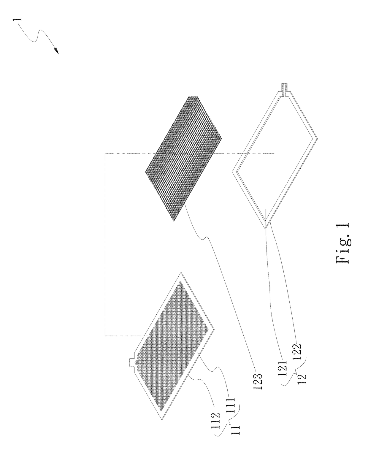
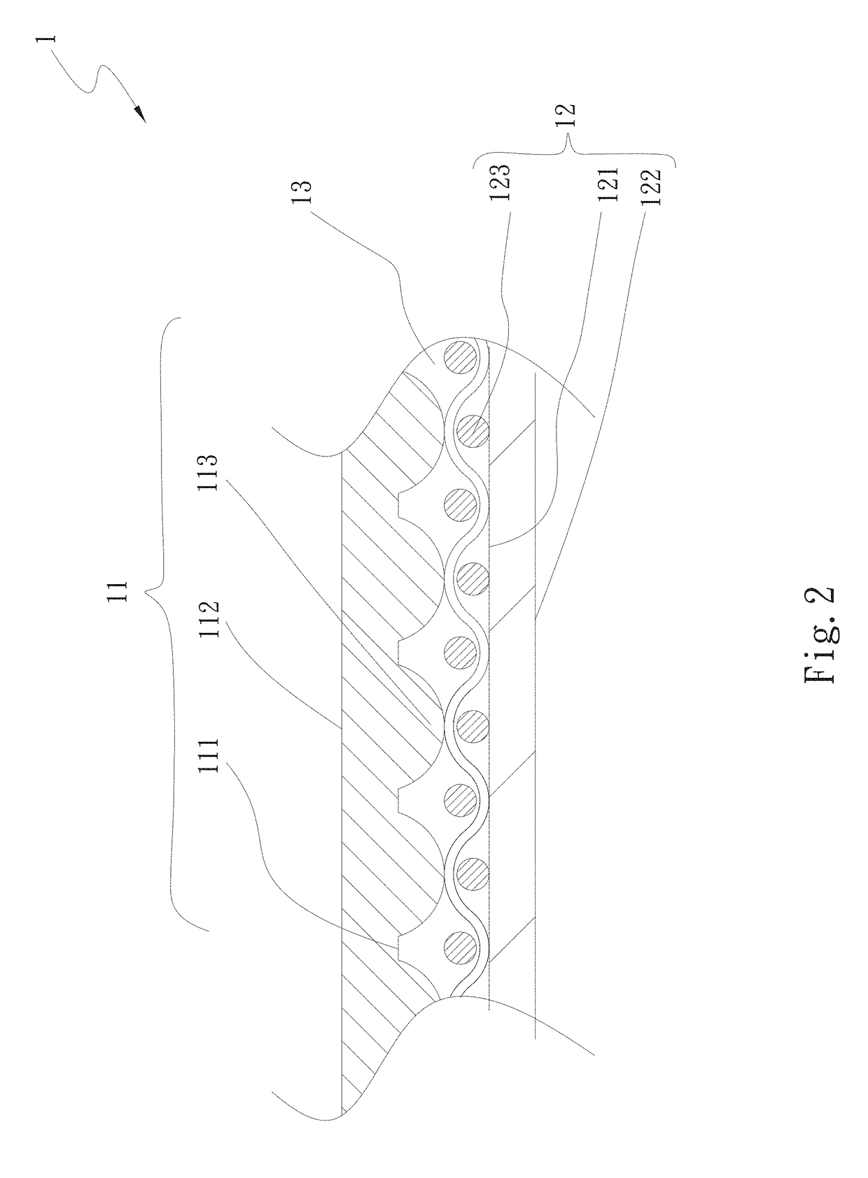
[0029]Please refer to FIGS. 1 and 2, which are exploded perspective and assembled sectional views, respectively, of a first embodiment of a heat dissipation device 1 according to the present invention. As shown, the illustrated first embodiment of the heat dissipation device 1 includes a first titanium metal sheet 11 and a second titanium metal sheet 12.

[0030]The first titanium metal sheet 11 has a first surface 111 and an opposite second surface 112. The first surface 111 has a plurality of raised sections 113 formed thereon by means of stamping. In the present invention, the second surface 112 serves as a condensing side of the heat dissipation device 1.

[0031]The second titanium metal sheet 12 has a third surfa...


PUM

PropertyMeasurementUnit
temperatureaaaaaaaaaa
poweraaaaaaaaaa
wavelengthaaaaaaaaaa

Abstract

A method of manufacturing a heat dissipation device is disclosed. The heat dissipation device manufactured with the method includes two titanium metal sheets, which are subjected to a heat treatment before undergoing mechanical processing, plastic working and surface modification. With these arrangements, the titanium metal sheets can be freely plastically deformed and possess a capillary force, and can therefore be used in place of the conventional copper material to serve as a material for making heat dissipation devices, and the heat dissipation devices so produced can have largely reduced weight and largely improved heat dissipation performance.

Description

FIELD OF THE INVENTION[0001]The present invention relates to a method of manufacturing a heat dissipation device, and more particularly to a heat dissipation device manufactured with pure titanium metal and a method of manufacturing same.BACKGROUND OF THE INVENTION[0002]The currently available electronic devices all have a largely increased computing speed, and as a result, the electronic elements in the electronic devices tend to produce a high amount of heat while operating. At least one heat dissipation unit, such as a heat pipe, a heat spreader, a vapor chamber or a radiator, is usually adopted by electronic device manufacturers to solve the problem of heat produced by the internal electronic elements. The heat dissipation unit can be directly in contact with or be associated with a heat-producing electronic element to carry the produced heat away from the electronic element. Or, a cooling fan can be further provided and connected to the heat dissipation unit to achieve forced h...

Claims


Application Information

Patent Timeline
Patent Type & Authority Applications(United States)
IPC IPC(8): B23P15/26C22F1/18C22F1/02B23K20/02C23C18/12B32B15/02B32B15/04B23K26/12B23K26/24F28F21/08F28D15/04F28F13/18
CPCB23P15/26B23K2103/14C22F1/02B23K20/023C23C18/1241C23C18/1254B32B15/02B32B15/04B23K20/02B23K26/123B23K26/24F28F21/086F28D15/046F28F13/187B32B2311/18F28F2245/02F28F2245/04B23K2101/14C22F1/183B23K26/32B23P2700/10B23K26/1224B23K26/60B23K2101/18B23K2101/36C23C18/1212C23C18/1216C23C18/1225
Inventor CHIANG, KUEI-FENGLIN, CHIH-YEH
Owner ASIA VITAL COMPONENTS SHENZHEN CO LTD
Why Eureka
Try Eureka