Eureka AIR delivers breakthrough ideas for toughest innovation challenges, trusted by R&D personnel around the world.

Chemical heat pump with multi-channel membrane reactor

Active Publication Date: 2019-01-03
SOUTH CHINA UNIV OF TECH
View PDF0 Cites 0 Cited by
  • Summary
  • Abstract
  • Description
  • Claims
  • Application Information

AI Technical Summary

Benefits of technology

The present invention is a device that uses a membrane to separate the product of a chemical reaction from the non-reacted product. This device is a multi-channel waste heat absorption membrane reactor in a temperature-boost chemical heat pump system. The device has improved heat efficiency and a high reaction conversion rate, which means it can produce a large amount of product in a short time. The system uses a circulation system to optimize heat utilization, resulting in a low-power consumption separation of the product. This device has a simple structure and is economically efficient. The use of a membrane instead of a distillation column in the system reduces energy consumption and improves heat efficiency. The chemical heat absorption reaction progressively continues in the multi-channel waste heat recovering membrane reactor, eliminating the need for a reboiler and condenser, and improving the conversion rate of the reaction.

Problems solved by technology

However, the separation effect is poor, and energy consumptions of the reboiler at the bottom of the distillation column and the condenser at the top of the distillation column are higher, which accounts for 45% to 65% of the total energy consumption of the temperature-boost chemical heat pump system.
Therefore, the temperature-boost chemical heat pump system has a low heat efficiency, which is generally lower than 16%.
The non-effective power consumption and heat consumption are relatively higher, which further hinders improvement of the heat efficiency of the temperature-boost chemical heat pump system.

Method used


Image

  • Chemical heat pump with multi-channel membrane reactor

Examples


Embodiment Construction

[0022]The objectives of the present invention are further described in detail with reference to the accompanying drawings and specific embodiments. The embodiments are not exhaustively described herein. However, the embodiments of the present invention are not limited to those described hereinafter.

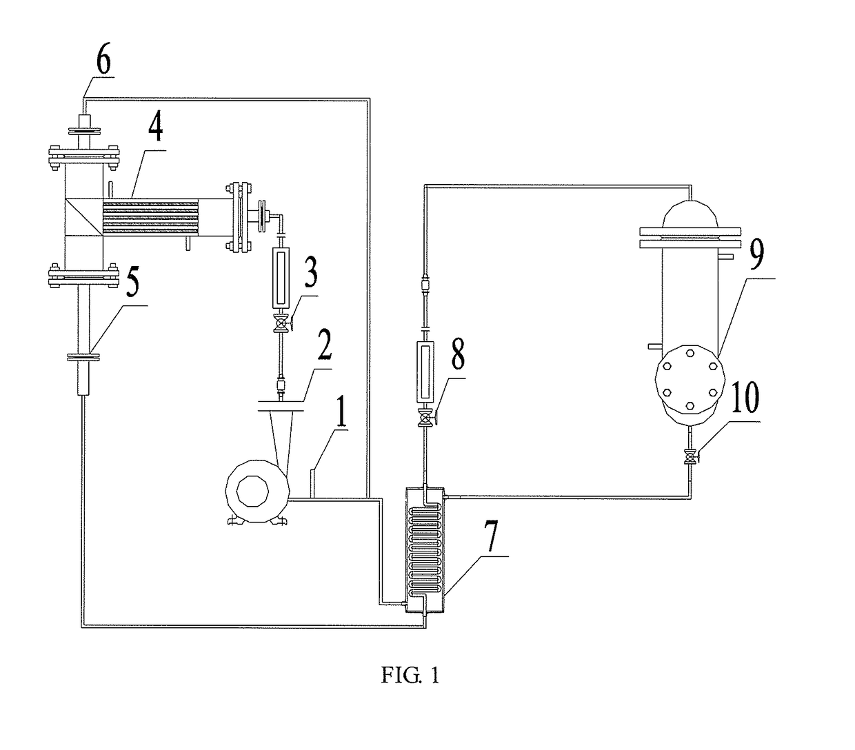
[0023]As illustrated in FIG. 1, a chemical heat pump with a multi-channel membrane reactor comprises: a feeding pipe 1, a liquid phase pump 2, a first solenoid valve 3, a multi-channel waste heat recovering membrane reactor 4, a discharging pipe 5, a remainder reflowing pipe 6, a heat regenerator 7, a second solenoid valve 8, a high-temperature heat release reactor 9, and a third solenoid valve 10. The feeding pipe 1 is sequentially connected to the liquid phase pump 2, the first solenoid valve 3, and a feeding port of the multi-channel waste heat recovering membrane reactor 4; and a discharging port of the multi-channel waste heat recovering membrane reactor 4 is sequentially connected t...


PUM


Abstract

The present invention provides a chemical heat pump with a multi-channel membrane reactor, comprising: a feeding pipe, a liquid phase pump, a first solenoid valve, a multi-channel waste heat recovering membrane reactor, a discharging pipe, a remainder reflowing pipe, a heat regenerator, a second solenoid valve, a high-temperature heat release reactor, and a third solenoid valve. The feeding pipe is sequentially connected to the liquid phase pump, the first solenoid valve, and a feeding port of the multi-channel waste heat recovering membrane reactor; and a discharging port of the multi-channel waste heat recovering membrane reactor is sequentially connected to the heat regenerator, the second solenoid valve, the high-temperature heat release reactor and the third solenoid valve via the discharging pipe, and is then connected to the heat regenerator and an inlet of the liquid phase pump, and a remainder reflowing port of the multi-channel waste heat recovering membrane reactor is reconnected to the inlet of the liquid phase pump via the remainder reflowing pipe. According to the present invention, a working medium subjected to the heat absorption reaction of the chemical heat pump is separated through a membrane, such that the heat consumption of a reboiler and the cold consumption of a condenser in a distillation column can be avoided, a sufficient separation is achieved, and the reaction conversion rate and the heat efficiency of a chemical heat pump system can be improved.

Description

TECHNICAL FIELD[0001]The present invention relates to innovative designs of temperature-boost chemical heat pumps, and in particular, relates to a temperature-boost chemical heat pump with a multi-channel membrane reactor which improves quality of waste heat.BACKGROUND[0002]A heat pump is to absorb heat from the surrounding environment, and transfer the heat to an object to be heated. A chemical heat pump refers to a heat pump that utilizes a chemical phenomenon, and also refers to a heat pump that utilizes a thermo-chemical reaction. The chemical heat pump may be categorized into three types: thermal storage type, heating type, and temperature-boost type. The temperature-boost heat pump improves the quality of the low-quality waste heat, such that the low-quality waste heat between 80° C. and 120° C. is converted into the high-to-medium-quality effective waste heat with a temperature of over 200° C.[0003]At present, a conventional temperature-boost chemical heat pump system general...

Claims


Application Information

Patent Timeline
IPC IPC(8): F25B30/04F25B30/06
CPCF25B30/04F25B30/06Y02B30/52F25B29/006Y02P80/15
Inventor FAN, SHUANSHIZHANG, WENXIANGLANG, XUEMEIWANG, YANHONG
Owner SOUTH CHINA UNIV OF TECH
Why Eureka
Eureka Blog
Learn More