
Methods of improving optical proximity correction models and methods of fabricating semiconductor devices using the same

a technology of optical proximity correction and fabrication method, which is applied in the direction of photomechanical treatment originals, instruments, photomechanical equipment, etc., can solve the problems of lithography process, small manufacturing design and pattern of semiconductor devices, and increase the integration density of semiconductor devices, so as to improve the reliability of the opc model and improve the opc model

Active Publication Date: 2019-01-03
SAMSUNG ELECTRONICS CO LTD
View PDF0 Cites 6 Cited by
  • Summary
  • Abstract
  • Description
  • Claims
  • Application Information

AI Technical Summary

Benefits of technology

The patent text describes methods for improving the reliability of an OPC model, which is a type of computer software used in industrial settings. These methods can help to optimize the model and make it more accurate, which can ultimately lead to better performance and reliability in industrial processes.

Problems solved by technology

To satisfy this demand, the complexity and / or integration density of semiconductor devices are being increased, resulting in smaller manufacturing designs and patterns for the semiconductor devices.
However, in a manufacturing design having a complex mask pattern or having a pattern with sharply changing sizes and line widths, a lithography process used to transfer the design to a semiconductor wafer may be affected by diffraction of light in adjacent patterns.
However, conventional OPC processes may be inefficient and / or may not sufficiently compensate for diffracted light.

Method used


Image

  • Methods of improving optical proximity correction models and methods of fabricating semiconductor devices using the same
  • Methods of improving optical proximity correction models and methods of fabricating semiconductor devices using the same
  • Methods of improving optical proximity correction models and methods of fabricating semiconductor devices using the same

Examples


Embodiment Construction

[0040]Example embodiments of the inventive concepts will now be described more fully with reference to the accompanying drawings, in which example embodiments are shown.

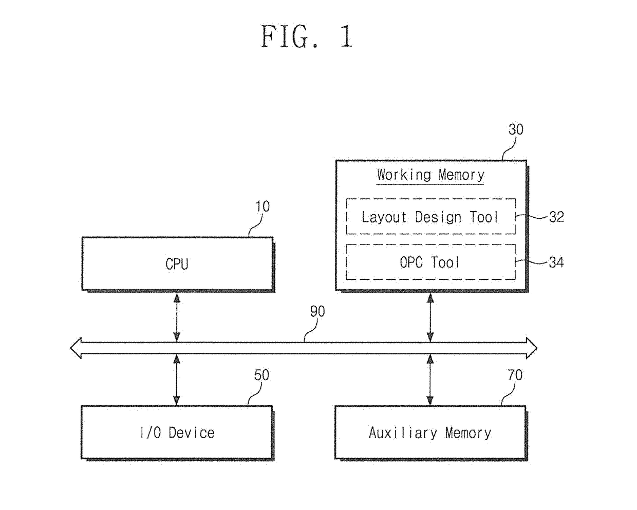
[0041]FIG. 1 is a block diagram illustrating a computer system for performing a semiconductor design process, according to some embodiments of the inventive concepts. Referring to FIG. 1, a computer system may include a central processing unit (CPU) 10, a working memory 30, an input-output device 50, and an auxiliary memory device 70. In some embodiments, the computer system may be a customized system for performing a layout design process according to some embodiments of the inventive concepts. Furthermore, the computer system may be configured to execute various design and check simulation programs.

[0042]The CPU 10 may be configured to run a variety of software programs, such as application programs, operating systems, and / or device drivers. For example, the CPU 10 may be configured to run an operating system (not ...


PUM


Abstract

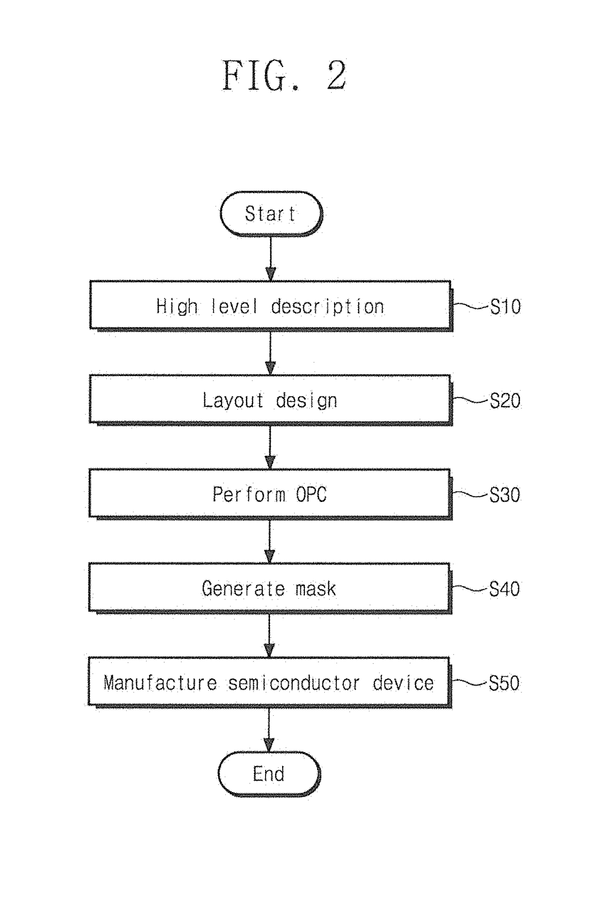
A method of fabricating a semiconductor device includes designing a layout, performing an optical proximity correction (OPC) process to correct the designed layout, fabricating a first photomask using the corrected layout, and forming patterns on a substrate using the first photomask. The OPC process includes generating an OPC model and correcting the designed layout using the generated OPC model. The generation of the OPC model includes rasterizing a planar image of an actual pattern to obtain first label data, rasterizing a simulation image of a simulation pattern to obtain second label data, the simulation pattern being obtained using the OPC model, in which a parameter set including process parameters is set, comparing the first label data with the second label data to obtain comparison data, and correcting the process parameters of the parameter set, based on the comparison data.

Description

CROSS-REFERENCE TO RELATED APPLICATIONS[0001]This U.S. non-provisional patent application claims priority under 35 U.S.C. § 119 to Korean Patent Application No. 10-2017-0083815, filed on Jun. 30, 2017, in the Korean Intellectual Property Office, the entire contents of which are hereby incorporated by reference herein.BACKGROUND OF THE INVENTION[0002]The present disclosure relates to methods of fabricating semiconductor devices, and in particular, to methods of fabricating semiconductor devices using an optimized and / or improved optical proximity correction (OPC) model.[0003]Due to their small size, multifunctional usage, and / or low-cost characteristics, semiconductor devices are important elements in the electronic industry. The semiconductor devices may be classified, for example, into a memory device for storing data, a logic device for processing data, and a hybrid device including both of memory and logic elements. To meet the increased demand for electronic devices with faster ...

Claims


Application Information

Patent Timeline
IPC IPC(8): G03F1/36G03F7/20G03F1/70G06F17/50H01L21/027
CPCG03F1/36G03F7/70441G03F1/70G06F17/5081H01L21/0274H01L21/0338H01L27/0207G03F7/705G03F7/704G03F7/70433G06F30/398
Inventor JEONG, MOON-GYU
Owner SAMSUNG ELECTRONICS CO LTD
Learn More