Resin-clad metal foil and flexible printed wiring board

Active Publication Date: 2019-02-28
PANASONIC INTELLECTUAL PROPERTY MANAGEMENT CO LTD +1
View PDF2 Cites 0 Cited by
  • Summary
  • Abstract
  • Description
  • Claims
  • Application Information

AI Technical Summary

Benefits of technology

The present invention provides a resin-clad metal foil and flexible printed wiring board that allows for reduced fluidity and extrusion of resin while maintaining good adhesiveness, bendability, thermal resistance, and circuit filling property.

Problems solved by technology

The printed board has, however, a surface which is provided with the copper pattern and is thus uneven.
Thus, when the hot pressing is performed with the thermoplastic resin sheet being provided, the unevenness of the surface of the printed board may result in an uneven surface of the metal foil of the perforated resin-clad metal foil.
When the surface of the metal foil is uneven and is no longer smooth, mounting components on the surface with a high density becomes difficult.
However, since the resin of the perforated resin-clad metal foil has a high degree of fluidity, the resin is extruded into the holes.

Method used


Image

  • Resin-clad metal foil and flexible printed wiring board
  • Resin-clad metal foil and flexible printed wiring board

Examples


example 1

[0069]Example 1 includes eleven examples, that is, Examples 1-(1) to 1-(11). These examples are the same except for only a second insulating layer.

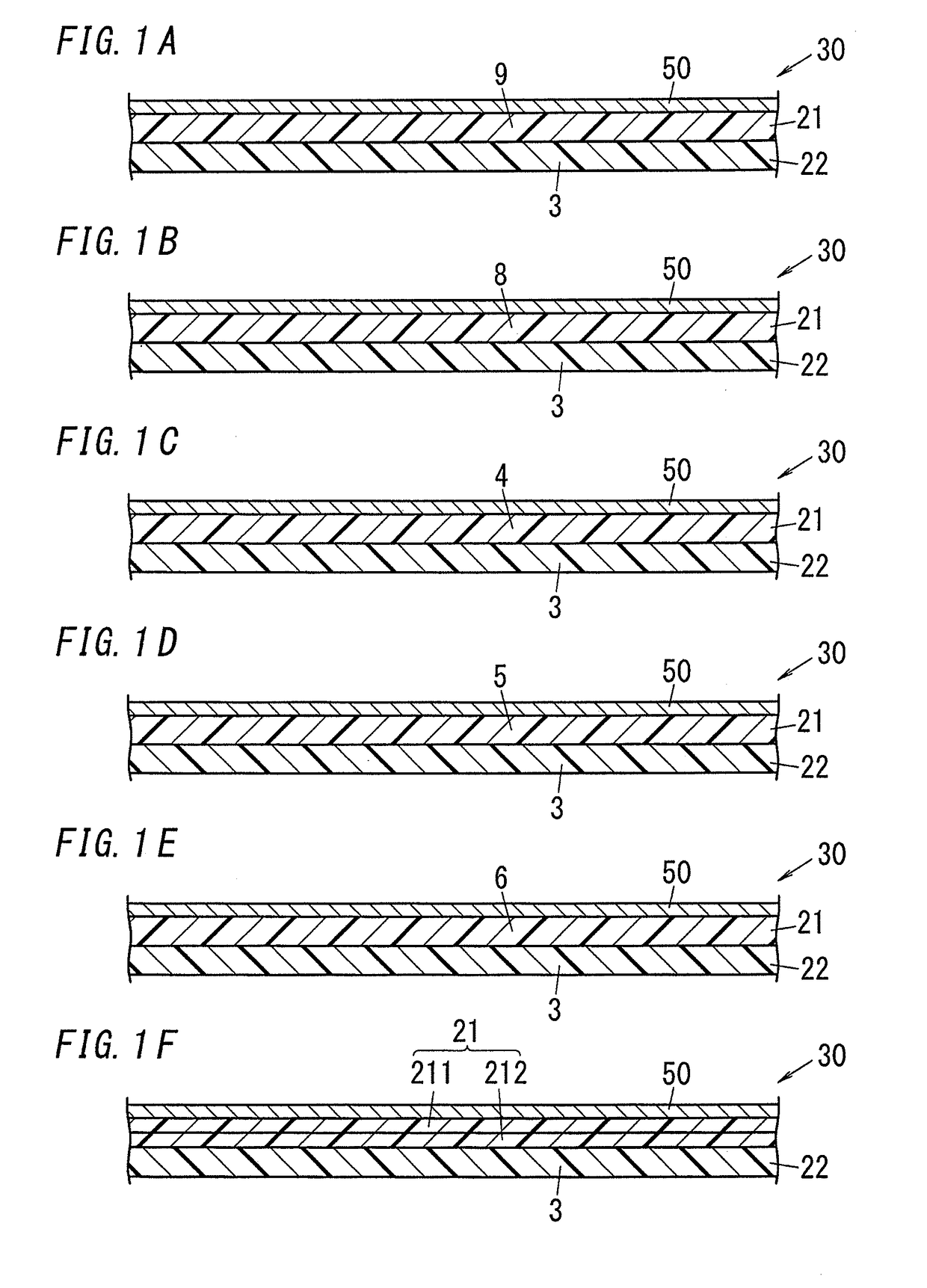
[0070]“R-F552” manufactured by Panasonic Corporation was prepared (“R-F552” is a two-layer casting flexible copper clad laminated board fabricated by applying a liquid polyimide resin composition to a surface of a copper foil and heating and drying the liquid polyimide resin composition, wherein the copper foil has a thickness of 12 μm, and a polyimide resin layer in a cured state has a thickness of 12.5 μm).

[0071]A polyolefin resin composition having a resin composition of each of (1) to (11) shown in Table 3 was applied to a surface of the polyimide resin layer, heated and dried to form a polyolefin resin layer which is in a semi-cured state and which has a thickness of 50 μm. Thus, a resin-clad metal foil including a first insulating layer (the polyimide resin layer in a cured state) and a second insulating layer (polyolefin resin laye...

example 2

[0072]A second example includes eleven examples, that is, Examples 2-(1) to 2-(11). These examples are the same except for only the second insulating layer.

[0073]A liquid polyamideimide resin composition was applied on a surface of a copper foil having a thickness of 12 μm and was heated and dried to form a polyamideimide resin layer which is in a cured state and which has a thickness of 12.5 μm.

[0074]The liquid polyamideimide resin composition was prepared as described below. A mixture was obtained by blending 192 g of trimellitic acid anhydride (manufactured by Nacalai Tesque, Inc.), 211 g of 4,4′-diisocyanate-3,3′-dimethyl biphenyl, 35 g of 2,4-diisocyanatotoluene, 1 g of diazabicycloundecene (San-Apro Ltd.), and 2482 g of N,N-dimethyl acetamide (DMAC, manufactured by Nacalai Tesque, Inc.) so as to realize a polymer concentration of 15 wt. %, and the thus obtained mixture was heated to 100° C. in 1 hour and was subsequently maintained at 100° C. for six hours to promote reaction....


PUM

PropertyMeasurementUnit
Temperatureaaaaaaaaaa

Abstract

A resin-clad metal foil which enables a reduction in fluidity of a resin during molding and a reduction in extrusion of the resin while maintaining good adhesiveness, bendability, thermal resistance, and circuit filling property. A first insulating layer includes a polyimide resin layer, a polyamideimide resin layer, a liquid crystal polymer resin layer, a fluororesin layer, or a polyphenylene ether resin layer and a second insulating layer includes a polyolefin resin layer in a semi-cured state are disposed in this order on a metal foil. The polyolefin resin layer contains a component representing a polyolefin-based elastomer and a component representing a thermosetting resin. The percentage by mass of the component in the polyolefin resin layer ranges from 50 wt. % to 95 wt. %.

Description

TECHNICAL FIELD[0001]The present invention relates to resin-clad metal foils and flexible printed wiring boards, and specifically to a resin-clad metal foil adopted in the fabrication of a printed wiring board such as a flexible printed wiring board and a flexible printed wiring board included in various electronic apparatuses.BACKGROUND ART[0002]Compact and thin electronic apparatuses include a large number of flexible printed wiring boards. To achieve higher-density and thinner electronic apparatuses, the flexible printed wiring boards having a multilayer structure have been more required. In addition, the flexible printed wiring boards are required to be of a higher quality. As materials for realizing multilayer structures of flexible printed wiring boards, bonding sheets or coverlays are adopted as insulating layers, and metal foils such as copper foils are adopted as conductive layers. To satisfy the demand for a reduction in thickness, a resin-clad metal foil has been proposed...

Claims


Application Information

Patent Timeline
IPC IPC(8): B32B15/088B32B15/08B32B27/08B32B27/28B32B27/32B32B27/42B32B27/34B32B15/20H05K1/03
CPCB32B15/088B32B15/08B32B27/08B32B27/281B32B27/32B32B27/42B32B27/34B32B27/322B32B15/20H05K1/0393H05K1/0373H05K1/036B32B2307/206B32B2307/202B32B2457/08H05K2201/0154H05K2201/0141H05K2201/015H05K2201/0158H05K2201/0195H05K2201/0209H05K3/4655B32B2255/26B32B3/08B32B2255/10B32B27/286B32B2307/306B32B2255/06B32B2307/546B32B2307/734B32B27/285B32B3/26B32B2307/406B32B2255/28B32B27/302B32B2307/51B32B15/085H05K1/03B32B2270/00
Inventor ISHIKAWA, YOHSUKEESAKI, YOSHIAKIOZEKI, TAKAYOSHITOCHIHIRA, JUNHARADA, RYU
Owner PANASONIC INTELLECTUAL PROPERTY MANAGEMENT CO LTD
Why Eureka
Try Eureka