Glass filler-reinforced solid resin
a filler-reinforced solid resin and glass technology, applied in the direction of coatings, etc., can solve the problems that the optical properties of filler-reinforced resin produced using simple and widely used processing methods, such as injection molding, extrusion, hot press molding, have not reached an acceptable level to replace glass and unfilled transparent resins, etc., to achieve better optical characteristics, better transmission, and higher brightness
- Summary
- Abstract
- Description
- Claims
- Application Information
AI Technical Summary
Benefits of technology
Problems solved by technology
Method used
Image
Examples
example 1
Formation of Samples
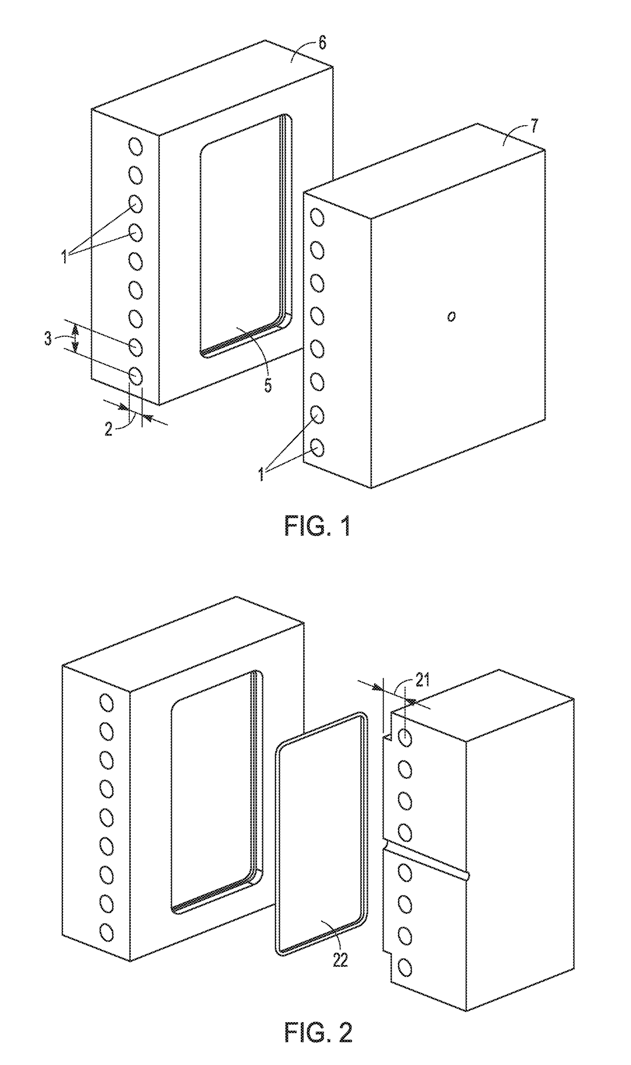
[0076]Double-sided dynamic temperature control injection molding tooling was polished using machining by grinder or end-mill, polishing wetstone from rough to smooth (from #1500 to #3000), then sand paper from rough to smooth (from #2000 to 3000), then lastly diamond compound #2 from Universal Superabrasives, USA. The final polished tooling had a smoothness of about Ra 6.5 nanometers. The tooling is illustrated in FIG. 1, with sides 6 and 7. The diameter 2 of the heating / cooling channels 1 was about 8 mm. The center of the heating / cooling channels 1 were located about 8 mm from the tool core surface 5. The distance 3 between the heating / cooling channels was about 16 mm. FIG. 2 shows a cross section of the molding tooling, showing molded part 22. The distance 21 was about 8 mm.
[0077]The injection molding tooling was used to generate a flat injection molded form using a glass fiber-filled 65:35 by weight mixture of bisphenol-A based polycarbonate having a refractiv...
example 2
Characterization of Samples
[0079]Total transmittance, scattered transmittance, and haze was measured using an HM-150 from Murakami Color Research Laboratory, which both used a Halogen D65 (CIE standard) light source at 380 nm to 780 nm. Brightness was measured with an SR-3A supplied by Topcon, which shines a xenon light source at the sample against a white plate and detects the reflected light from the sample and from the white plate through the sample. Surface roughness was measured using a Contour Elite I from Bruker.
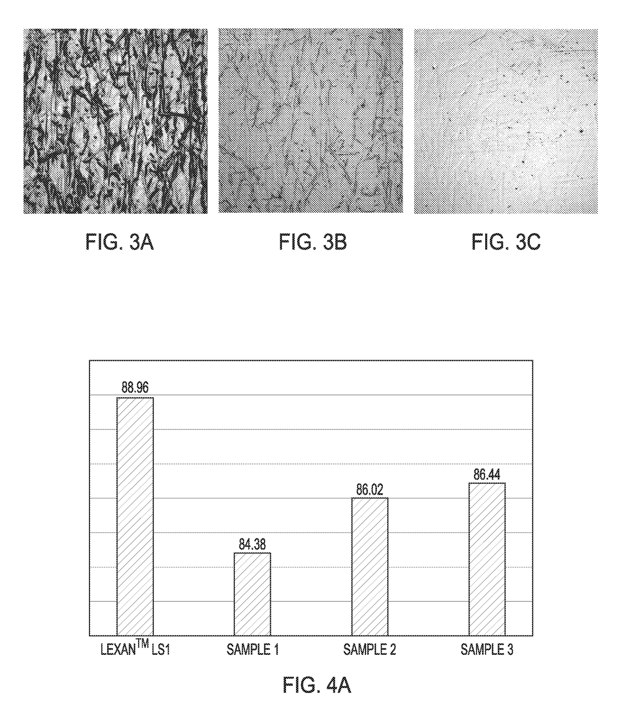
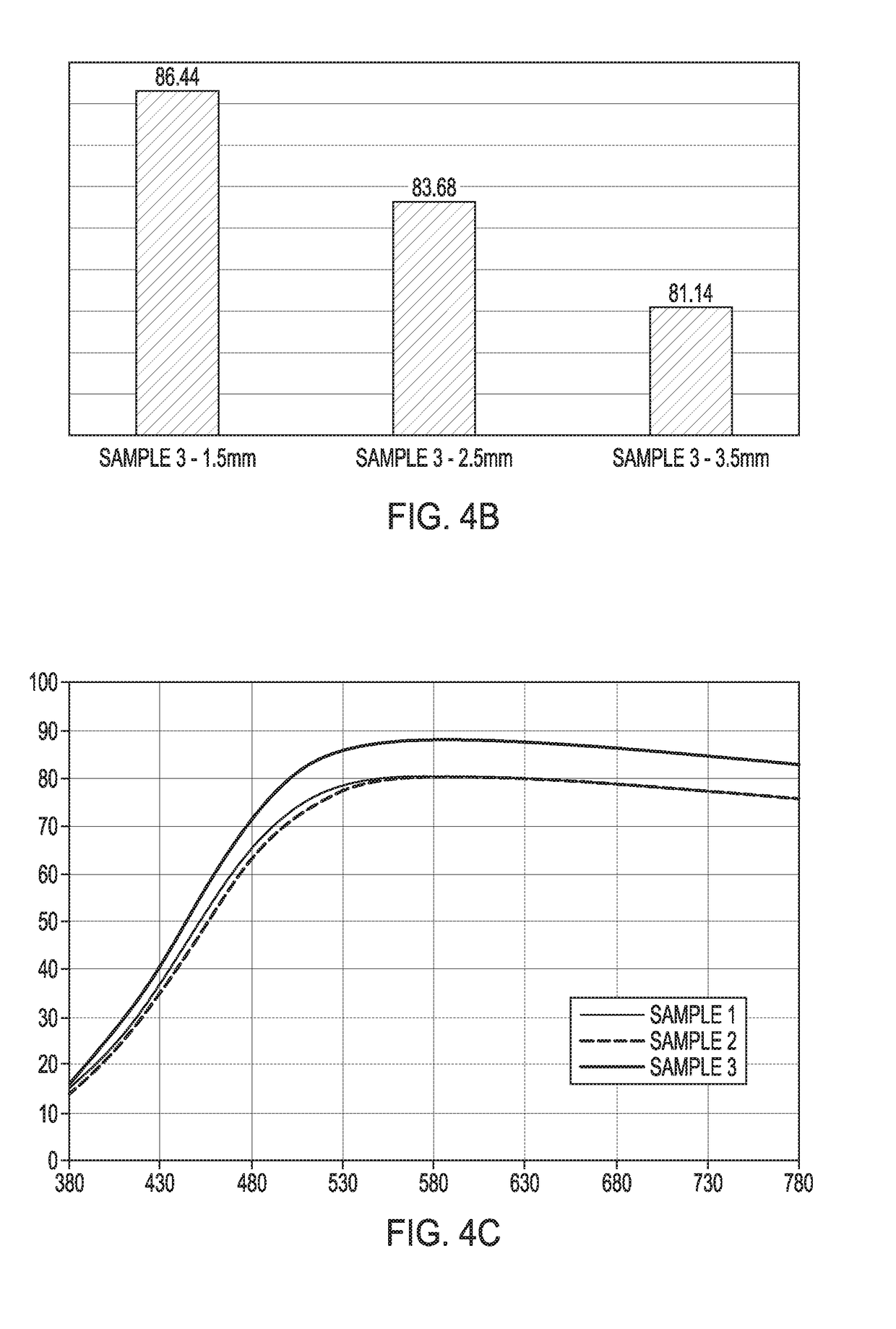
[0080]FIG. 4A illustrates total transmittance at 380-780 at 1.5 mm thickness for Samples 1-3, compared to Lexan™ LSI. Total transmittance was improved for Samples 2 and 3, with the double-sided heating and cooling of Sample 3 providing the best result. FIG. 4B illustrates total transmittance for Sample 3 at 1.5 mm, 2.5 mm, and 3.5 mm thickness. As thickness decreased, total transmittance increased. FIG. 4C illustrates the total transmittance including scattered transm...
PUM
| Property | Measurement | Unit |
|---|---|---|
| Length | aaaaa | aaaaa |
| Length | aaaaa | aaaaa |
| Fraction | aaaaa | aaaaa |
Abstract
Description
Claims
Application Information
 - R&D
- Intellectual Property
- Life Sciences
- Materials
- Tech Scout
- Unparalleled Data Quality
- Higher Quality Content
- 60% Fewer Hallucinations
Browse by: Latest US Patents, China's latest patents, Technical Efficacy Thesaurus, Application Domain, Technology Topic, Popular Technical Reports.
© 2025 PatSnap. All rights reserved.Legal|Privacy policy|Modern Slavery Act Transparency Statement|Sitemap|About US| Contact US: help@patsnap.com


