
Processing parameter and resource sharing architecture for superchannel based transmission systems

Active Publication Date: 2019-03-14
XIEON NETWORKS SARL
View PDF11 Cites 2 Cited by
  • Summary
  • Abstract
  • Description
  • Claims
  • Application Information

AI Technical Summary

Benefits of technology

The patent describes a system that takes digital signals and processes them to improve the transmission of optical carriers. The system uses digital processing units to adjust the signals based on certain parameters. The frequency band of the system is set to a width of 800 GHz or less, preferably 400 GHz or less. This narrowing of the band width helps the carriers to share processing parameters more efficiently, which can increase processing efficiency and decrease processing time.

Problems solved by technology

However, this modulation scheme is extremely sensitive to the optical signal-to-noise ratio (OSNR), which is a limiting factor for the transmission performance.
However, in practice the highest baud rates currently achievable are in fact on the order of 30 Gbaud, due to the limited speed of the available digital electronics.
However, this only allows for a moderate increase in the data transmission rate up to approximately 200 Gb / s per channel.
The derivation of the processing parameters by means of the corresponding parameter derivation procedure can be quite demanding both with regard to processing time and computing power.
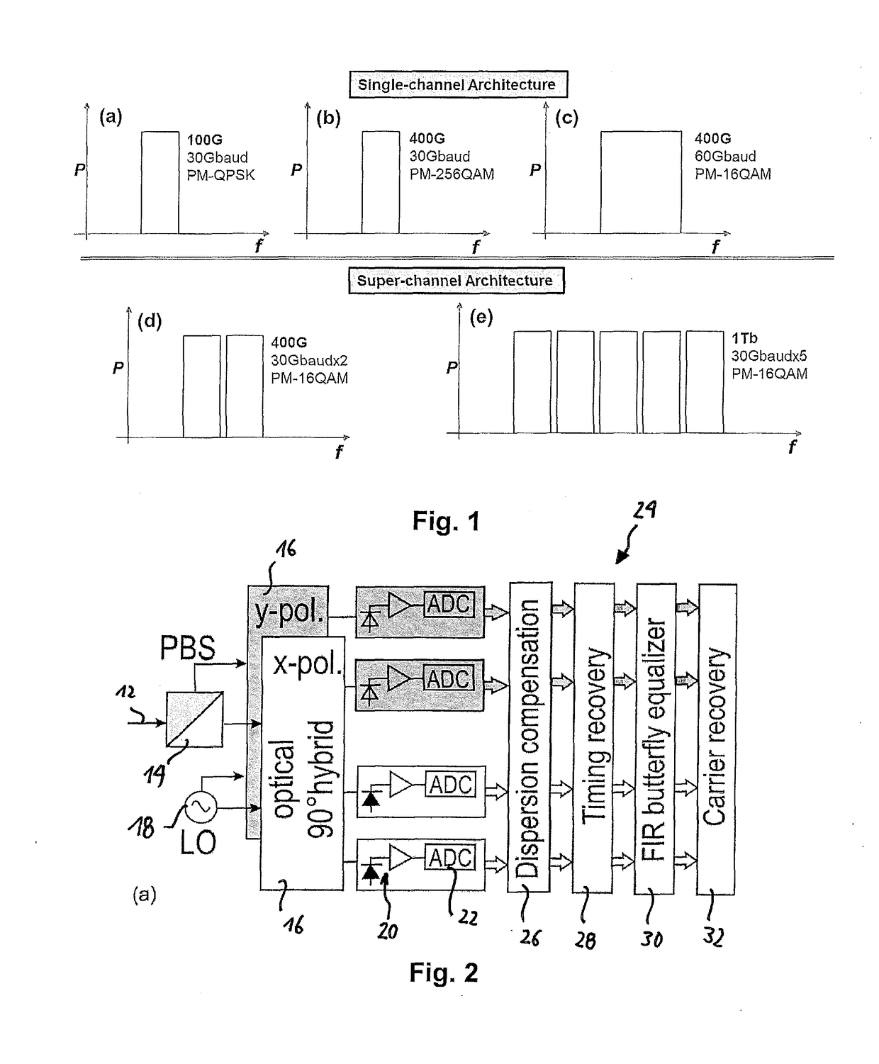
When using multi-channels as shown in FIGS. 1(d) and 1(e), although the multichannel is regarded as “one channel” from the network point of view, still the digital processing described above needs to be carried out for each of the carriers of the super channel, thereby leading to an even further increased demand for processing power and also electrical energy consumption.

Method used


Image

  • Processing parameter and resource sharing architecture for superchannel based transmission systems
  • Processing parameter and resource sharing architecture for superchannel based transmission systems
  • Processing parameter and resource sharing architecture for superchannel based transmission systems

Examples


Embodiment Construction

[0055]For the purposes of promoting an understanding of the principles of the invention, reference will now be made to a preferred embodiment illustrated in the drawings, and specific language will be used to describe the same. It will nevertheless be understood that no limitation of the scope of the invention is thereby intended, such alterations and further modifications in the illustrated apparatus and such further applications of the principles of the invention as illustrated therein being contemplated as would normally occur now or in the future to one skilled in the art to which the invention relates.

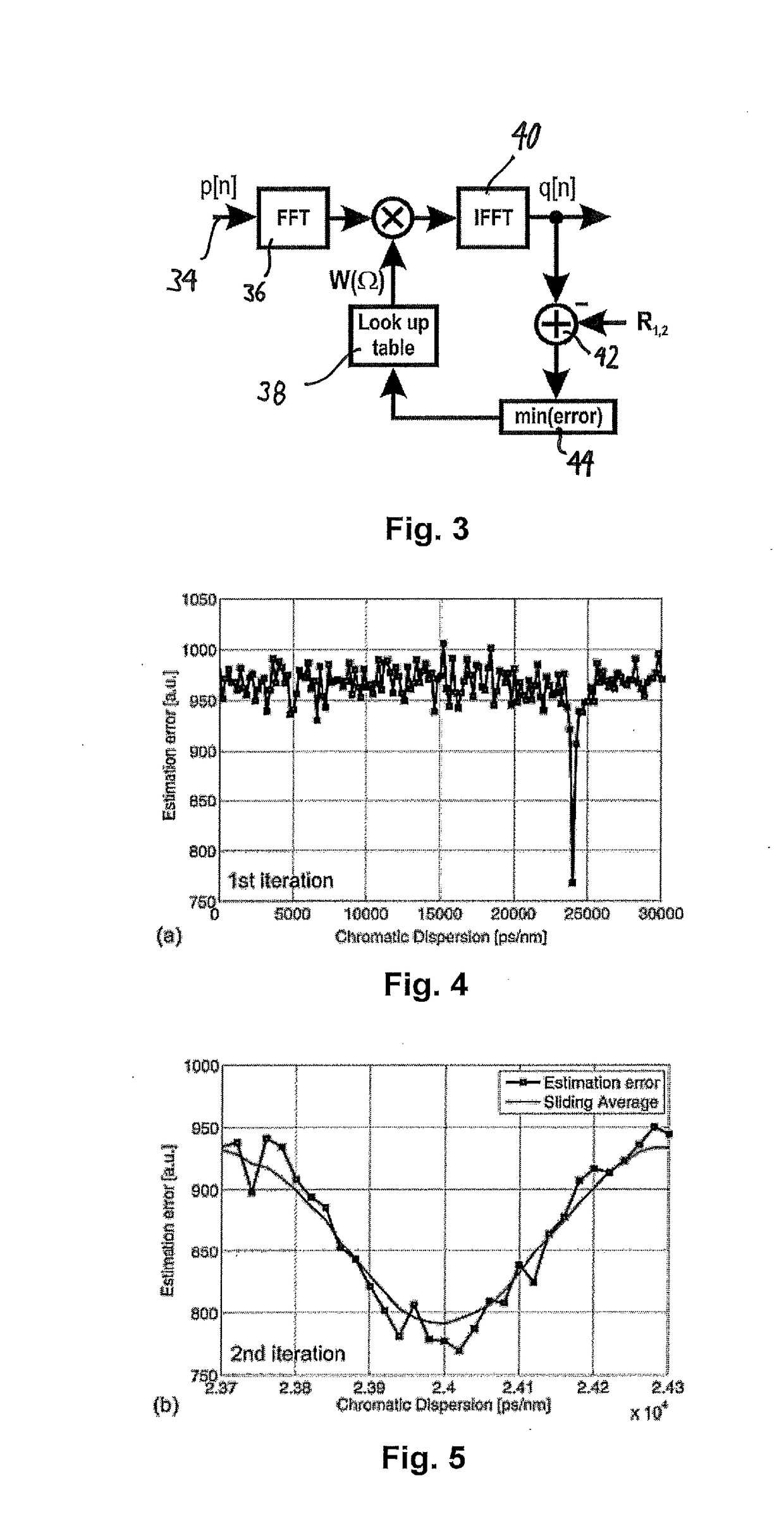
[0056]FIG. 3 is a schematic diagram showing an example of a prior art algorithm for processing a digital signal for estimating and compensating chromatic dispersion. A detailed description of this algorithm is provided in “Adaptive Chromatic Dispersion Equalization for Non-Dispersion Managed Coherent Systems” by M Kuschnerov, F. N. Hauske, K Piyawanno, B. Spinnler, A. Napoli, B. L...


PUM


Abstract

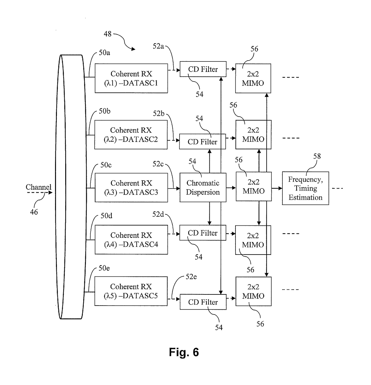
Disclosed is a receiver for receiving an optical signal comprising a plurality of carriers within a predetermined frequency band. The receiver comprises means for sampling and converting each of the carriers into a set of corresponding digital signals, and a digital processing unit for processing said digital signals of said set of digital signals such as to mitigate transmission impairments of the corresponding optical carriers based on corresponding processing parameters. The digital processing unit is configured for determining such processing parameters by carrying out a corresponding parameter derivation procedure based on one of the digital signals of said set of digital signals. The processing unit is configured for sharing thus determined processing parameters for processing of other digital signals among said set of digital signals based on said shared determined processing parameters, or processing parameters derived from said shared determined processing parameters.

Description

FIELD OF THE INVENTION[0001]The present invention is in the field of optical data transmission. Critically, the invention relates to a receiver for receiving an optical signal comprising a plurality of carriers, and a related receiving method.BACKGROUND OF THE INVENTION[0002]In optical networks using coherent carriers, currently available data transfer rates are on the order of 100 Gb / s per channel. As indicated in FIG. 1(a), a data transfer rate of 100 Gb / s can e.g. be achieved using polarization division multiplexing quaternary phase shift keying (PM-QPSK) with a symbol rate of 30 Gbaud. In FIGS. 1(a) to 1(e), the horizontal axis represents the frequency and the vertical axis the signal power.[0003]In order to increase the data transmission rates, either higher order modulation formats or higher baud rate transmission systems could in principle be employed. For example, as indicated in FIG. 1(b), a data transmission rate of 400 Gb / s can be obtained by using a PM-256QAM modulation ...

Claims


Application Information

Patent Timeline
IPC IPC(8): H04J14/06H04B10/61H04L27/20
CPCH04J14/06H04B10/6164H04B10/6162H04B10/6163H04L27/2082H04B10/616H04J14/02H04B10/60
Inventor RAFIQUE, DANISHSPINNLER, BERNHARD
Owner XIEON NETWORKS SARL
Learn More