
High flow low pressure suction device

a high-pressure suction device and low-pressure technology, applied in the field of fluid mechanics, can solve the problems of system not fit for mobile robots, friction between rubber skirts (seals, etc., and achieve the effects of reducing fluid pressure, increasing the velocity of incoming air, and reducing fluid energy

Active Publication Date: 2019-03-28
WCB ROBOTICS INC
View PDF0 Cites 7 Cited by
  • Summary
  • Abstract
  • Description
  • Claims
  • Application Information

AI Technical Summary

Benefits of technology

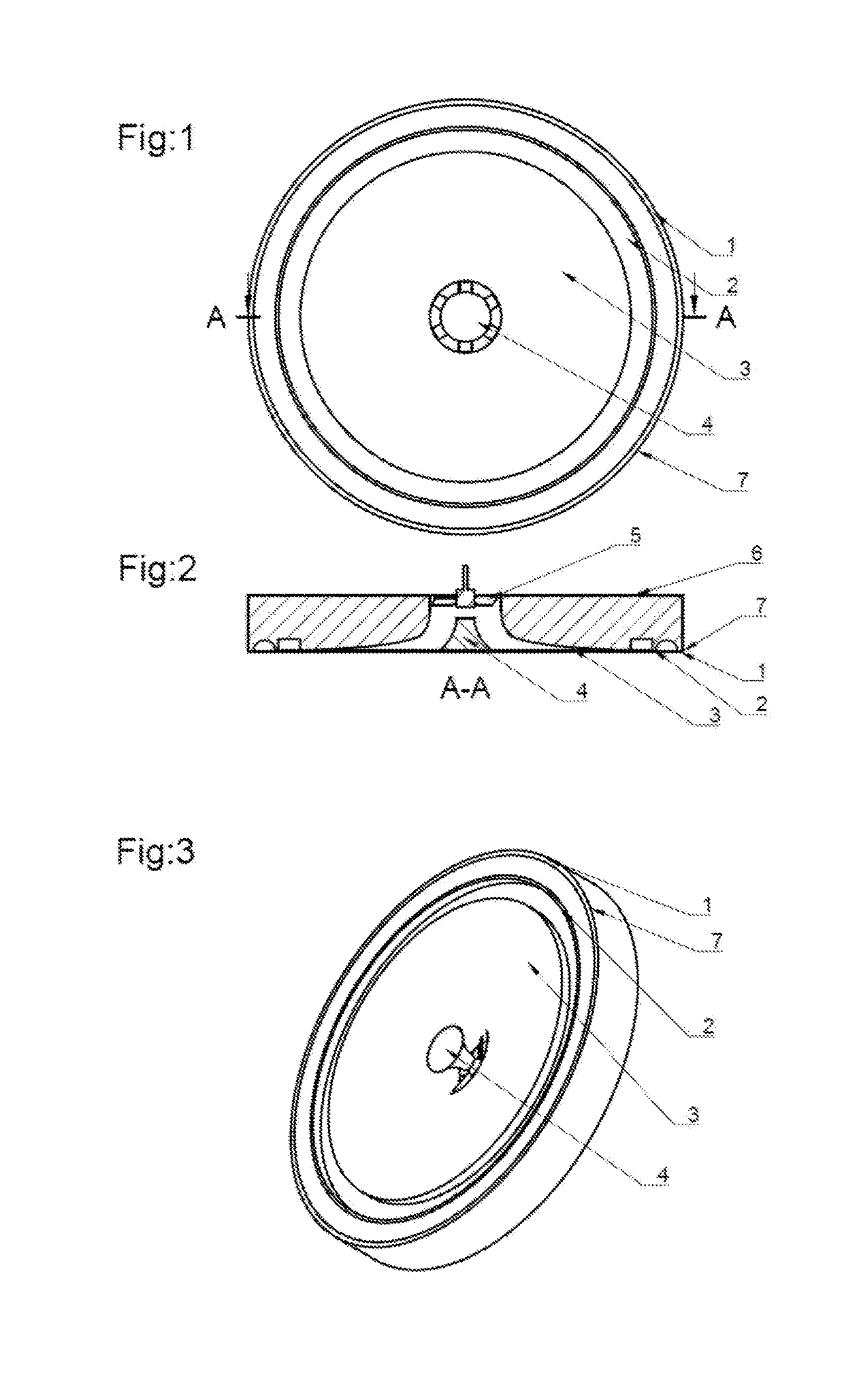
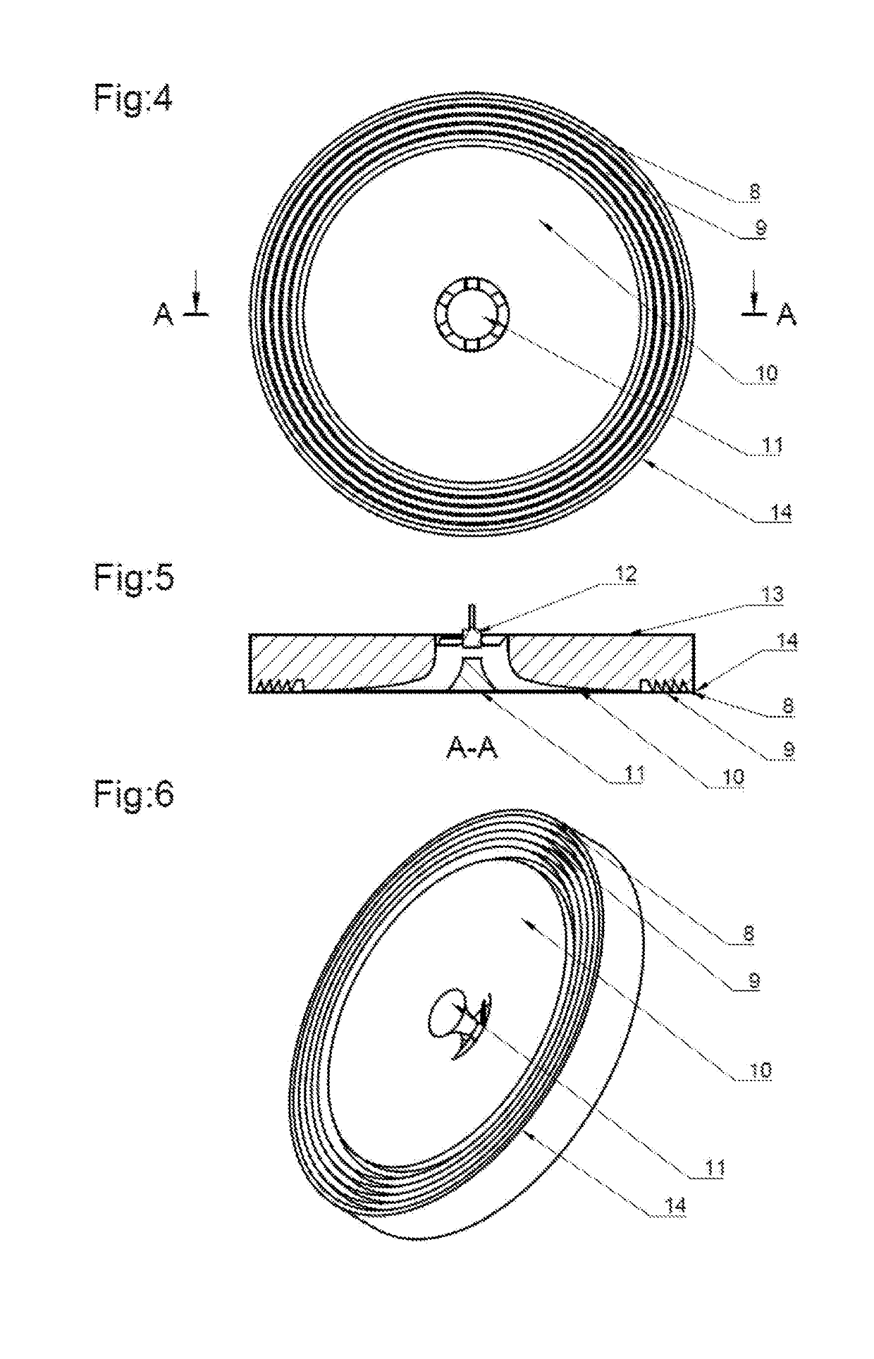
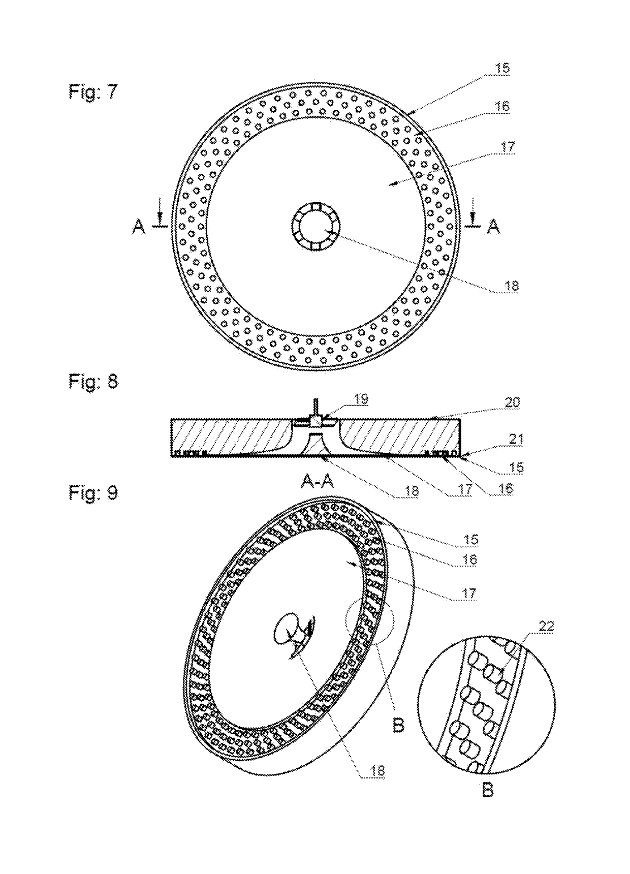
The present invention is a non-contact suction device that can work with any fluids and slurries including gases and liquids. The device has a unique design that includes an acceleration zone, a turbulence zone, and a smooth zone. The acceleration zone increases the velocity of the air or fluid and induces some turbulence, which helps to decrease the fluid pressure. The turbulence zone induces turbulence in the air or fluid and reduces its energy. The smooth zone has a special geometry that minimizes the change in the area of cross-section for the air or fluid, providing a constant cross-section area to be faced by the air or fluid. The non-contact suction device performs robustly in situations of varying roughness and surface texture.

Problems solved by technology

However, these systems are not fit for mobile robots especially on rough surfaces.
This technology faces several problems.
One of the major problems is the friction between the rubber skirt (seal (in dragged seal form)) and the surface.
This hinders motion and may also leave rubber marks on walls.
Also, if due to certain non-uniformity in the surface (on which the robot is moving) the seal leaves contact then the air pressure will be lost and catastrophic failure will result (applicable for both, dragged seal type and the walking type).
Also, they always operate in the risk of the impeller striking some surface protrusion hence damaging the surface and the impeller.

Method used


Image

  • High flow low pressure suction device
  • High flow low pressure suction device
  • High flow low pressure suction device

Examples


Embodiment Construction

[0078]The present invention relates to high flow low pressure suction device. Particularly, the invention belongs to the field of fluid mechanics which describes a suction mechanism and / or device involving multiple stage turbulence based high flow low pressure suction that does not need to contact the sucked surface. The suction device of the present invention produces non-contact suction in a new and more efficient manner. The word non-contact does not claim that no portion of the suction mechanism can touch the surface. It only means that a proper seal with the surface is not required.

[0079]The device can be used to suck, suspend, hold, lift and interrupt an object. The device can also be used to adhere to a surface as needed in wall climbers. The device can be used alone or in conjugation with other mechanical or electronic systems. The device can work with any fluids and slurries including gasses (e.g. air), liquids (e.g. water), or any combination thereof, slurries, or any othe...


PUM


Abstract

The present invention discloses a high flow low pressure suction device. The device is a non-contact suction device based on multiple stage turbulence based low pressure suction mechanism which comprises fan(s) or rotating impeller(s) for drawing air / fluid / slurries operates without any seal between the device and the sucked surface. The device compounds this turbulence based low pressure generation along with Bernoulli's principle to yield a high efficiency suction device. The device implements the above concept by making the air / fluid / slurries flow through two or three zones selected from the acceleration zone(s), turbulence zone(s) (high turbulence zone) and smooth zone(s) (minimum turbulence zone). The device works by pulling the air / fluid / slurries into the vacuum chamber, accelerating the air / fluid / slurries, creating turbulence in the air / fluid / slurries in a thin region near the perimeter in order to cause a drop in pressure and then maintaining pressure over a large bottom area and finally exhausting the air / fluid / slurries through the fan(s) / rotating impeller(s).

Description

FIELD OF THE INVENTION[0001]The present invention relates to high flow low pressure suction device. Particularly, the invention belongs to the field of fluid mechanics which describes a suction mechanism and device involving multiple stage turbulence based high flow low pressure suction that does not need to contact the sucked surface. This suction device can be used in wall climbers and other mobile robots or toys for slanted, vertical or upside-down surfaces. The device can also be used as an end effector for a manipulator. Another important use may be in devices requiring high traction such as airplane pushback tractors.BACKGROUND OF THE INVENTION[0002]The invention relates to the field of high flow low pressure suction device based on non-contact suction mechanisms. These devices have found profound use in mobile robots that are capable of moving on all surfaces regardless of the orientation. Wall climbing robots have commercial uses in making wall painting robots, window cleani...

Claims


Application Information

Patent Timeline
IPC IPC(8): F04D29/40F04D13/02F04D25/08B65G47/91F15D1/00
CPCF04D29/40F04D13/021F04D25/08B65G47/91F15D1/008B62D57/024A47L11/38B25J15/0683A47L1/02A47L11/40A47L2201/00
Inventor AGGARWAL, UJJAWAL
Owner WCB ROBOTICS INC
Learn More