Wireless inductive power transfer

a technology of inductive power transfer and wireless, which is applied in the direction of transmission, electrical equipment, circuit arrangements, etc., can solve the problems of increasing the weight, potential cost and size of the device, and the use of batteries, so as to achieve effective resonance frequency adjustment, facilitate implementation, and improve performance

Active Publication Date: 2019-03-28
KONINKLJIJKE PHILIPS NV
View PDF1 Cites 14 Cited by
  • Summary
  • Abstract
  • Description
  • Claims
  • Application Information

AI Technical Summary

Benefits of technology

[0045]This may provide improved performance in many scenarios, and may in particular provide an effective adjustment of the resonance frequency. The approach may facilitate implementation. The energy flow may be impeded while being from the capacitive impedance to the inductive impedance, from the...

Problems solved by technology

However, this tends to be impractical and requires the user to physically insert connectors or otherwise establish a physical electrical contact.
Although, the use of internal batteries may avoid the need for a wired connection to a power supply during use, this only provides a partial solution as the batteries will need recharging (or replacing).
The use of batteries may also add substantially to the weight and potentially cost and size of the devices.
However, in many scenarios, such an approach may not provide optimized performance.
Typically, modulation of high power signals tends to be more difficult than modulation of low power signals.
In particular, load modulation tends to be impractical for high power signals and in particular may introduce significant losses.
However, the re...

Method used


Image

  • Wireless inductive power transfer
  • Wireless inductive power transfer
  • Wireless inductive power transfer

Examples


Embodiment Construction

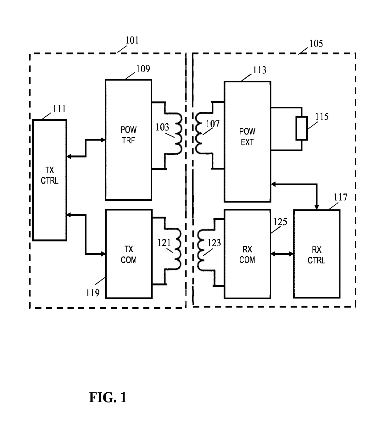
[0095]The following description focuses on embodiments of the invention applicable to a wireless power transfer system utilizing a power transfer approach such as that currently envisaged for kitchen applications by the Kitchen Work Group of the Wireless Power Consortium (WPC). However, it will be appreciated that the invention is not limited to this application but may be applied to many other wireless power transfer systems.

[0096]FIG. 1 illustrates an example of a power transfer system in accordance with some embodiments of the invention. The power transfer system comprises a power transmitter 101 which includes (or is coupled to) a transmitter inductor / coil, henceforth referred to as a power transfer transmitter coil 103. The system further comprises a power receiver 105 which includes (or is coupled to) a receiver coil / inductor, henceforth referred to as a power transfer receiver coil 107.

[0097]The system provides a wireless inductive power transfer from the power transmitter 10...


PUM


Abstract

A wireless power transfer system comprises a power transmitter (101) arranged to wirelessly power a power receiver (103) via an inductive signal. The power transmitter (101) comprises a variable resonance circuit for generating the inductive signal in response to a drive signal. The resonance circuit has a variable resonance frequency and comprises a transmitter coil (121) arranged to generate the inductive signal. A driver (707) generates the drive signal for the variable resonance circuit and a modulator (711) amplitude modulates the inductive signal by varying the variable resonance frequency in response to data values for transmission to the power receiver (105). The power receiver (105) comprises a demodulator (1105) for demodulating amplitude modulation of the inductive signal and a first power extractor (1113) for extracting power from the inductive signal and for powering at least part of the power receiver. The inductive signal may be provided in addition to a higher power main power transfer signal.

Description

FIELD OF THE INVENTION[0001]The invention relates to inductive power transfer and in particular, but not exclusively, to a power transmitter providing inductive power transfer using elements compatible with the Qi Specifications for wireless power transfer systems.BACKGROUND OF THE INVENTION[0002]Most present day systems require a dedicated electrical contact in order to be powered from an external power supply. However, this tends to be impractical and requires the user to physically insert connectors or otherwise establish a physical electrical contact. Typically, power requirements also differ significantly, and currently most devices are provided with their own dedicated power supply resulting in a typical user having a large number of different power supplies with each power supply being dedicated to a specific device. Although, the use of internal batteries may avoid the need for a wired connection to a power supply during use, this only provides a partial solution as the batt...

Claims


Application Information

Patent Timeline
IPC IPC(8): H02J50/12H02J50/80H04B5/00
CPCH02J50/12H02J50/80H04B5/0031H04B5/0037H04B5/0075
Inventor ETTES, WILHELMUS GERARDUS MARIA
Owner KONINKLJIJKE PHILIPS NV
Why Eureka
Try Eureka