Regenerative valve hydraulic actuator

Active Publication Date: 2019-04-04
RABHI VIANNEY
View PDF1 Cites 2 Cited by
  • Summary
  • Abstract
  • Description
  • Claims
  • Application Information

AI Technical Summary

Benefits of technology

[0034]In this regard, the regenerative valve hydraulic actuator according to the invention is in particular intended to implement on any reciprocating internal combustion engine most of the strategies that make it possible to maximize torque and power, on the one hand, and to reduce fuel consumption and emission of pollutants, on the other hand, said strategies being based on precise and flexible control of the intake and/or exhaust valves of said engine.
[0035]Thanks to the regenerative valve hydraulic actuator according to the invention, this significant improvement in the performance of said engines can be obtained without significantly increasing either the acoustic emissions or the manufacturing unit cost thereof.
[0036]It is also understood that the regenerative valve hydraulic actuator according to the invention is in particular designed

Problems solved by technology

Numerous “camless” devices have been produced which for the most part have stalled at the prototype stage.
A wide variety of devices have stalled at the design stage and have been implemented only partially, if at all.
At present, no “camless” type device has been mass produced for motor vehicles.
Moreover, the energy balance of numerous “camless” devices is in the final analysis mediocre because either the energy invested to accelerate the valve and to compress the return spring is not recovered at all or only too little or the energy efficiency of the hydraulic, electromagnetic or mechanical “camless” actuator is insufficient.
For example, U.S. Pat. No. 5,410,994 from inventor Michael M. Schechter does not recover the hydraulic energy invested to open the valve, to the point that the inventor even specifies in the text of said patent that the flow rate of hydraulic fluid feeding the valve is the main factor determining the energy consumption of the system.
Apart from leading to high energy consumption, non-recovery of the kinetic energy of the valve or of the valve return spring compression energy—whatever the nature of said spring—implies great instability of said valve, which forms with the hydraulic fluid a mass-spring system subjected to high excitation if the non-recovered energy is not entirely dissipated in the form of heat.
This is why many “camless” devices are imprecise and lead to unstable lifting and holding opening of the valve, whi

Method used


Image

  • Regenerative valve hydraulic actuator
  • Regenerative valve hydraulic actuator
  • Regenerative valve hydraulic actuator

Examples


Embodiment Construction

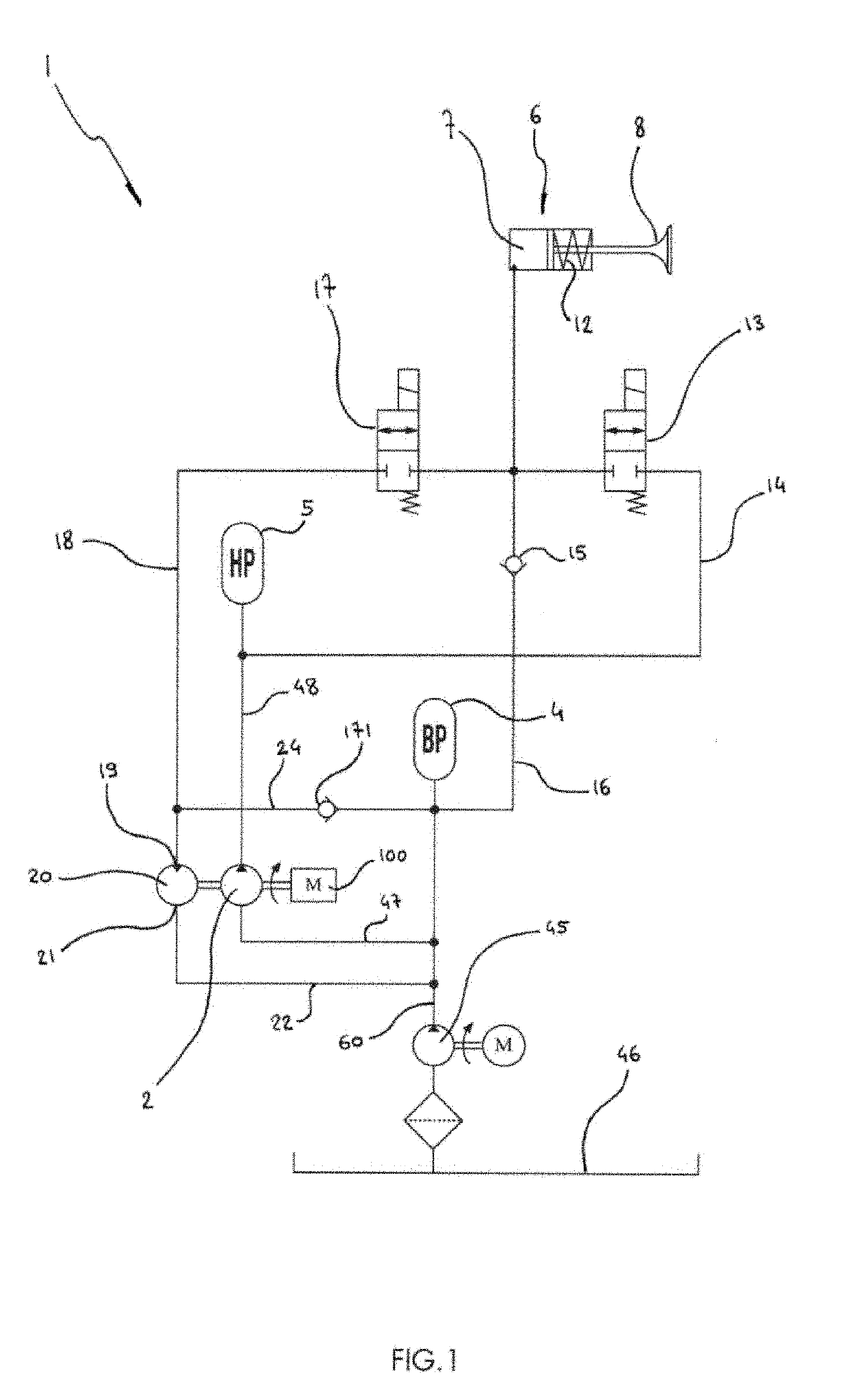
[0098]There have been shown in FIGS. 1 to 35 the regenerative valve hydraulic actuator 1, various details of its components, its variants, and its accessories.

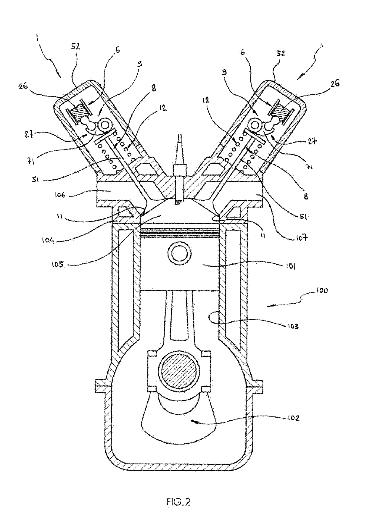
[0099]As FIG. 2 illustrates, the regeneration valve hydraulic actuator 1 is particularly intended for a reciprocating piston compressor or engine 100 which comprises at least one piston 101 connected to transmission means 102 to reciprocate in a cylinder 103 closed by a compressor or engine cylinder head 104.

[0100]Still in FIG. 2, it is seen that the piston 101, the cylinder 103 and the compressor engine cylinder head 104 form a compressor or combustion chamber 105 into which open at least one intake line 106 and at least one exhaust or discharge line 107, one or both of said lines 106, 107 being connected to said chamber 105 by a line orifice 10 which a valve 8 is able to block when it rests on a valve seat 11.

[0101]As FIG. 1 and FIGS. 5 to 12 particularly illustrate, the regenerative valve hydraulic actuator 1 according to t...


PUM


Abstract

A regenerative valve hydraulic actuator includes a high-pressure accumulator fed by a high-pressure feed hydraulic pump, an actuator defining an actuator hydraulic chamber for actuating—by way of a progressive lever arm ratio lever—a valve provided with a valve return device, a valve lifter hydraulic valve placed between the high-pressure accumulator and the actuator hydraulic chamber, a lifter check valve which connects a low-pressure accumulator to the actuator hydraulic chamber, a valve closure hydraulic valve placed between the chamber and a closure and regeneration hydraulic motor which recovers energy previously invested to open the valve.

Description

BACKGROUND OF THE INVENTIONField of the Invention[0001]The present invention relates to a regenerative valve hydraulic actuator which is particularly intended for use in reciprocating internal combustion engines.Description of the Related Art[0002]Since the early days of internal combustion engines, numerous devices have been designed to actuate opening and closing of the intake and exhaust valves of the most widely used internal combustion engines, that is to say those employing a Beau de Rochas, Otto or Diesel cycle.[0003]However, because of its reliability, its robustness, its simplicity and its moderate unit cost, the camshaft has been imposed as the virtually universal valve actuator equipping almost all four-travel engines produced worldwide.[0004]For all that, the cams which said camshaft includes have a profile fixed by their design which leaves no freedom to change the valve lift laws that said cams actuate.[0005]A first step toward more flexibility was made by inserting a ...

Claims


Application Information

Patent Timeline
IPC IPC(8): F01L9/02F16K31/122F01L9/11F01L9/10
CPCF01L9/021F16K31/1225F16K31/1223F01L1/08F01L1/181F01L1/185F01L3/12F01L2301/02F01L9/10F01L9/11
Inventor RABHI, VIANNEY
Owner RABHI VIANNEY
Why Eureka
Try Eureka