Time-reversed nonlinear acoustics for downhole pressure measurements
a nonlinear acoustic and pressure measurement technology, applied in the field of time-reversed nonlinear acoustics for downhole pressure measurement, can solve the problems of blowout, the most expensive and dangerous problem, and the force of the drill string ou
- Summary
- Abstract
- Description
- Claims
- Application Information
AI Technical Summary
Benefits of technology
Problems solved by technology
Method used
Image
Examples
example 1
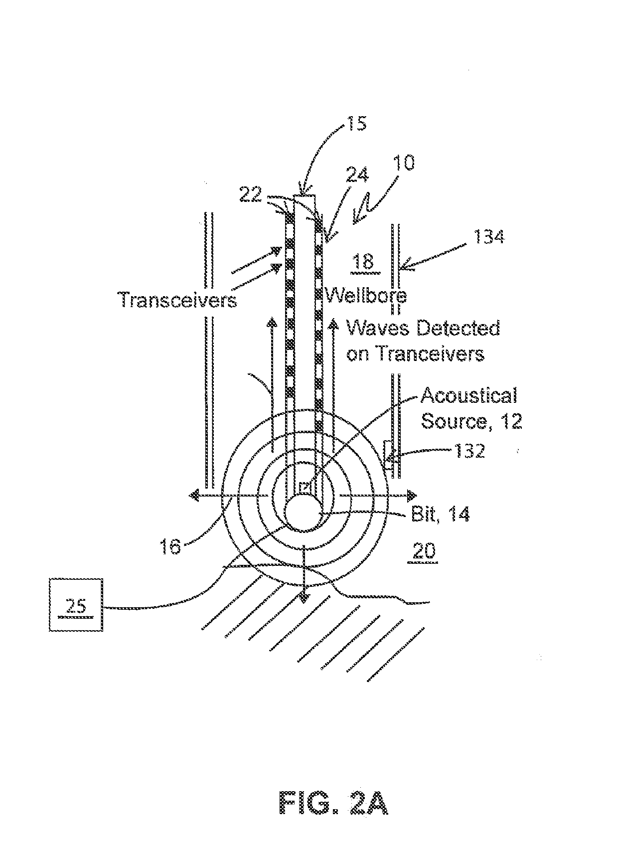
[0045]FIG. 6 is a schematic representation of an apparatus for carrying out reciprocal time reversal measurements described above in the laboratory for a simulated down hole environment. Pipe, 100, was embedded in block, 102, of Berea Sandstone. Ten acoustic transceivers 22 were affixed to portion, 104, of pipe 100 emerging from block 102. A reference signal, for example, a pulsed (10-20 kHz) sinusoidal waveform having a 50 kHz bandwidth, is directed into at least one arbitrary waveform generator, 106, by computer 38. After amplification by at least one power amplifier, 108, each generator signal is directed to a single transceiver 22, one generator signal at a time. The signal traveling through pipe 100 and block 102 is recorded by laser vibrometer, 110, after being received by fiber optic attachment, 112, disposed inside pipe 100. The signal received for each emission is digitized by digitizer, 114, and directed to computer 38, which time reverses each of the received signals and ...
example 2
Propagation of an Impulsive Elastic Waveform in a Long, Thin Bar
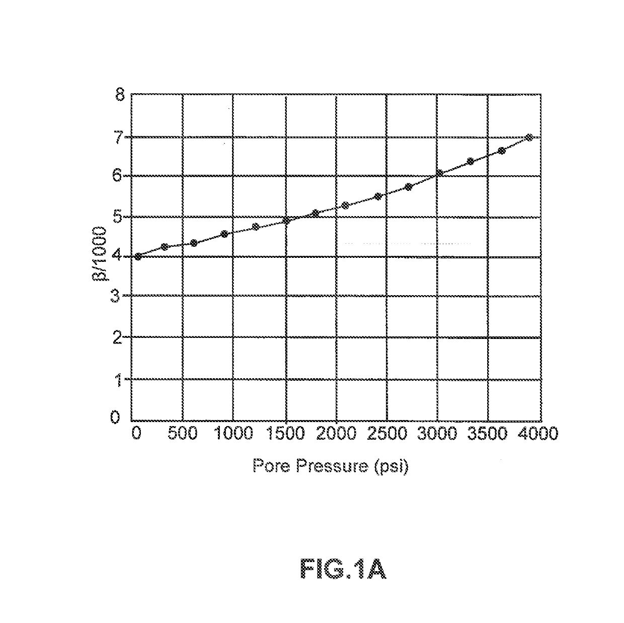
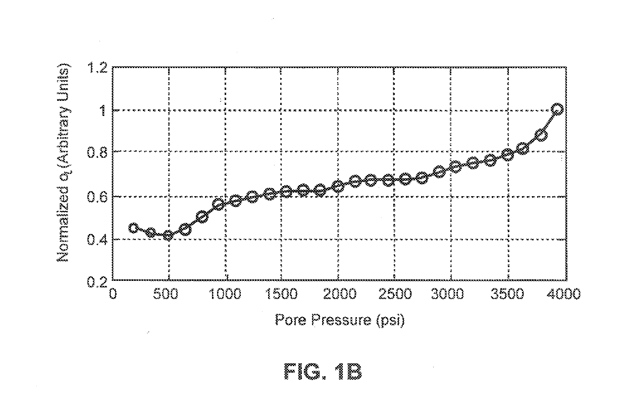
[0052]As discussed above, with the aid of time reversal, elastic wave energy is focused at a point in space and an impulsive waveform will be generated. Since this process involves waves traveling through materials, and material properties may be strain dependent, the arrival time of the impulsive waveform may be dependent on the amplitude of the excitation. The term of hysteretic nonlinearity a in the equation of state (Equ. 3) governs this effect.
[0053]To verify α can be quantified by monitoring the propagation speed of an elastic wave as a function of the strain amplitude, laboratory experiments were performed. Although the propagation of impulsive elastic waves remains the principal measurement, time reversal is not required to generate the strain since the measurements are restricted to a one-dimensional waveguide over a known propagation distance. The hysteretic nonlinearity parameter has never been measured in th...
example 3
Nonlinear Resonant Ultrasound Spectroscopy:
[0059]Returning to FIG. 10, with minor modifications, the apparatus may be utilized for resonant ultrasound spectroscopy. Sample, 120, of Berea sandstone (Cleveland Quarries, Amherst, Ohio) having a length of 1794 mm (70.63 in) and a diameter of 39.6 mm (1.56 in) is shown. The sample was supported by a foam pad, not shown in FIG. 10. Piezoelectric transducer 122 was driven with a sequence of harmonic voltage signals. Each harmonic signal was applied for 55 ms, and the transient vibrational response was recorded during the last 40 ms of the source signal, to ensure that steady state conditions had been reached. Vibrational spectra were constructed from the harmonic responses. Frequencies ranging between 0.3 kHz and 7 kHz in steps of 2.5 Hz were employed, and at 22 excitation amplitudes ranging between 0.25 to 10 Vpp (before amplification). The axial component of the acceleration was measured on the flat end opposite to the source by an accel...
PUM
 Abstract
Description
Claims
Application Information
 - R&D
- Intellectual Property
- Life Sciences
- Materials
- Tech Scout
- Unparalleled Data Quality
- Higher Quality Content
- 60% Fewer Hallucinations
Browse by: Latest US Patents, China's latest patents, Technical Efficacy Thesaurus, Application Domain, Technology Topic, Popular Technical Reports.
© 2025 PatSnap. All rights reserved.Legal|Privacy policy|Modern Slavery Act Transparency Statement|Sitemap|About US| Contact US: help@patsnap.com


