Cooling Spiral Groove Bearing Assembly

a technology of spiral groove bearings and assembly methods, which is applied in the direction of electrical discharge tubes, x-ray tube anode cooling, etc., can solve the problems of high demands on bearings, difficult surface manufacturing, and high reactive and corrosive liquid metals, so as to increase the turbulence of cooling fluid flowing, maximize heat transfer, and enhance heat exchange

Active Publication Date: 2019-04-04
GENERAL ELECTRIC CO
View PDF0 Cites 3 Cited by
  • Summary
  • Abstract
  • Description
  • Claims
  • Application Information

AI Technical Summary

Benefits of technology

[0012]In the present invention a liquid metal or spiral groove bearing structure for an x-ray tube and associated process for manufacturing the bearing structure is provided that includes a bearing shaft rotatably disposed in a bearing housing or shell. The shell includes a thrust seal engaged with a sleeve to maintain coaxiality for the rotating liquid metal seal formed in the shell about the shaft. The shaft has a bore for the introduction of a cooling fluid into the bearing assembly in which is disposed a cooling tube. The cooling tube includes turbulence-inducing features to increase the turbulence of the cooling fluid flowing through the cooling tube, consequently enhancing the heat exchange between the cooling fluid and the shaft. This maximizes the heat transfer from the shaft to the oil, allowing materials with lower thermal conductivities, such as non-refractory materials, to be used to form the bearing shaft and shell.

Problems solved by technology

This places stringent demands on the bearings and the material forming the anode structure, i.e., the anode target and the shaft supporting the target.
However, liquid metals tend to be highly reactive and corrosive.
However, as the refractory materials are difficult to machine, these surfaces are hard to manufacture without surface imperfections that enable leaks to occur in the seals.
Also, due to the low galling / wear properties of the refractory materials, these surface imperfections, even if not present after machining, can occur during normal use of the tube resulting in the formation of fluid leaks, thereby shortening the useful life of the tube.
However, one drawback to steel is that it has a much lower thermal conductance and a higher coefficient of thermal expansion compared to molybdenum.
Therefore the steel is more prone to thermal gradients and resulting non-uniform bearing deflections, which can lower bearing load carrying capability.
In this configuration, the amount of heat exchange that occurs between the cooling oil and the shaft is insufficient to counteract the lower thermal conductivity of steel, such that refractory metals are required for the construction of the bearing shaft in order to withstand the temperatures created when the bearing structure is in operation.

Method used


Image

  • Cooling Spiral Groove Bearing Assembly
  • Cooling Spiral Groove Bearing Assembly
  • Cooling Spiral Groove Bearing Assembly

Examples


Embodiment Construction

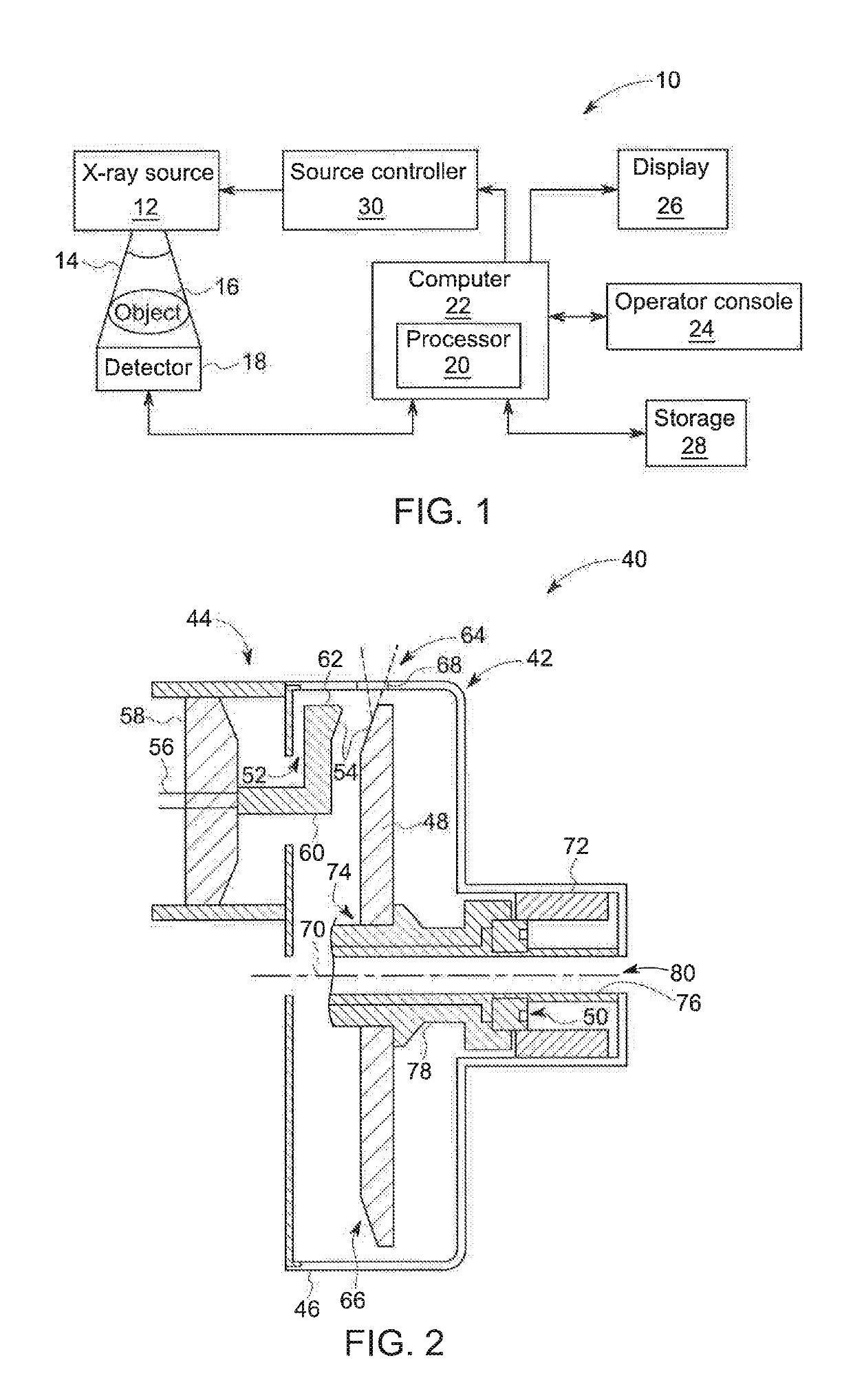
[0023]FIG. 1 is a block diagram of an embodiment of an imaging system 10 designed both to acquire original image data and to process the image data for display and / or analysis in accordance with embodiments of the invention. It will be appreciated by those skilled in the art that various embodiments of the invention are applicable to numerous medical imaging systems implementing an x-ray tube, such as x-ray or mammography systems. Other imaging systems such as computed tomography (CT) systems and digital radiography (RAD) systems, which acquire image three dimensional data for a volume, also benefit from the invention. The following discussion of x-ray system 10 is merely an example of one such implementation and is not intended to be limiting in terms of modality.

[0024]As shown in FIG. 1, imaging system 10 includes an x-ray tube or source 12 configured to project a beam of x-rays 14 through an object 16. Object 16 may include a human subject, pieces of baggage, or other objects des...


PUM


Abstract

A liquid metal or spiral groove bearing structure for an x-ray tube and associated process for manufacturing the bearing structure is provided that includes a bearing shaft rotatably disposed in a bearing housing or shell. The shell includes a thrust seal engaged with a sleeve to maintain co-axiality for the rotating liquid metal seal formed in the shell about the shaft. The shaft has a bore for the introduction of a cooling fluid into the bearing assembly in which is disposed a cooling tube. The cooling tube includes turbulence-inducing features to increase the turbulence of the cooling fluid flowing through the cooling tube, consequently enhancing the heat exchange between the cooling fluid and the shaft. This maximizes the heat transfer from the shaft to the oil, allowing materials with lower thermal conductivities, such as non-refractory materials, to be used to form the bearing shaft and shell.

Description

BACKGROUND OF THE INVENTION[0001]The invention relates generally to x-ray tubes, and more particularly to structures and methods of assembly for the spiral groove bearing (SGB) utilized in an x-ray tube.[0002]X-ray systems may include an x-ray tube, a detector, and a support structure for the x-ray tube and the detector. In operation, an imaging table, on which an object is positioned, may be located between the x-ray tube and the detector. The x-ray tube typically emits radiation, such as x-rays, toward the object. The radiation passes through the object on the imaging table and impinges on the detector. As radiation passes through the object, internal structures of the object cause spatial variances in the radiation received at the detector. The detector then emits data received, and the system translates the radiation variances into an image, which may be used to evaluate the internal structure of the object. The object may include, but is not limited to, a patient in a medical i...

Claims


Application Information

Patent Timeline
Patent Type & Authority Applications(United States)
IPC IPC(8): H01J35/10
CPCH01J35/106H01J35/101H01J2235/1204H01J2235/1262H01J2235/127H01J2235/1283H01J35/104H01J35/107
Inventor KRUSE, KEVIN SHANE
Owner GENERAL ELECTRIC CO
Why Eureka
Try Eureka