Force sensor, particularly for a touch pad

Active Publication Date: 2019-04-04
THE SWATCH GRP RES & DEVELONMENT LTD
View PDF0 Cites 1 Cited by
  • Summary
  • Abstract
  • Description
  • Claims
  • Application Information

AI Technical Summary

Benefits of technology

The patent describes a sensor that uses a ferromagnetic plate to detect swisses on a touch pad. The plate moves relative to the sensor and reduces the resistance of a magnetic circuit. The sensor is placed between the finishing wall and the pad to determine where the swimmer touches it. The use of amorphous metal for the plate provides advantages like high magnetic permeability and low magnetic creep. This allows for precise timing and low energy consumption. The sensor is protected from impacts and water. The technical effects of the patent are improved accuracy and efficiency in detecting sw акт

Problems solved by technology

A disadvantage of this type of sensor is that it does not allow the point on the pad at which the swimmer exerted a pressure to be located.
Another disadvantage is that a significant force has to be exerted on the pad in order for the metal strips to come into contact.

Method used


Image

  • Force sensor, particularly for a touch pad

Examples


Embodiment Construction

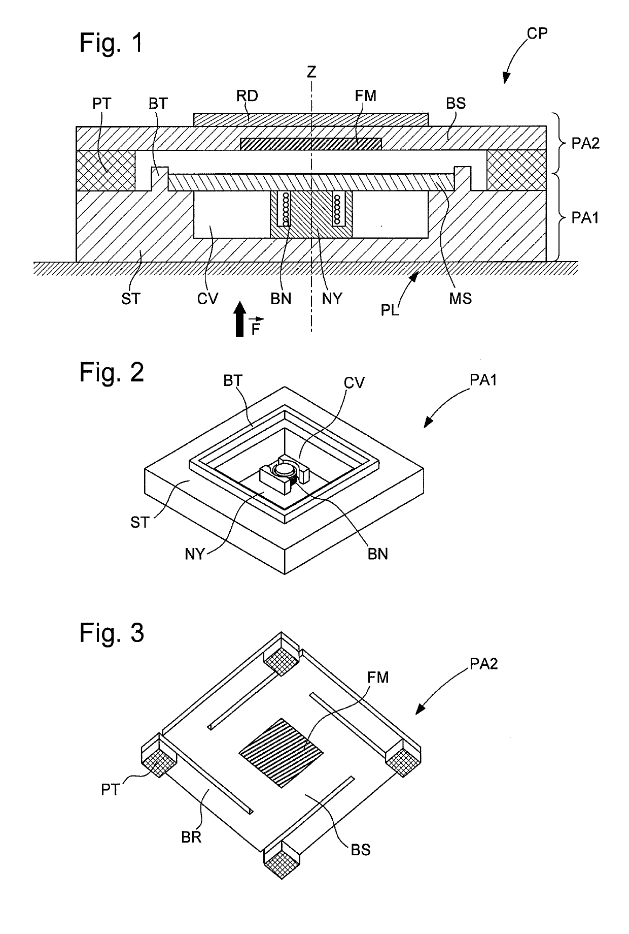
[0036]As shown with reference to FIG. 1, a force sensor CP according to the invention comprises:[0037]a first part PA1 particularly comprising a coil BN and a detection circuit (not shown) connected to the terminals of the coil BN;

[0038]a second part PA2, opposite the first part PA1, particularly comprising a ferromagnetic plate FM made of amorphous metal alloy, particularly of the 2714A type based on cobalt-iron-nickel-boron-silicon (Co69Fe4Ni1B4Si15).

[0039]The term “opposite” is understood to mean that the plane R along which the amorphous metal plate FM extends is substantially orthogonal to the axis Z of the coil BN.

[0040]In the embodiment shown in FIG. 1, the first part PA1 and the second part PA2 are fixed to each other. More specifically, and as described in further detail hereafter, the second part PA2 comprises suspension means BR, PT that are fixed to the first part PA1. The amorphous metal plate FM is kept suspended relative to the coil BN by means of these suspension mea...


PUM


Abstract

A force sensor including: a first part including a detection coil; a second part positioned opposite the first part and including: a ferromagnetic plate translationally movable relative to the first part to move towards the first part when a force is transferred to the sensor and to reduce reluctance of a magnetic circuit formed by the first and second parts in series with a variable gap; and an electronic detection circuit configured to generate a signal dependent on the reluctance of the magnetic circuit. The ferromagnetic plate is formed by an amorphous metal alloy.

Description

FIELD OF THE INVENTION[0001]The invention relates to a sensor suitable for detecting a force exerted on a pad, called touch pad, of a swimmer timing system. Such a sensor also can be considered to be a detector of a movement of the pad caused by the application of the force. Of course, even though the force / movement sensor is particularly suitable for the aforementioned use, it is suitable for all types of applications requiring the detection of a force or a movement.BACKGROUND OF THE INVENTION[0002]Conventionally, a touch pad is fixed to the finishing wall of a lane of a swimming pool. When a swimmer exerts a pressure thereon that is detected by a force sensor, a timer measuring the time of the swimmer stops or records an intermediate time.[0003]Force sensors suitable for this use are known from application U.S. Pat. No. 3,584,169. This application discloses force sensors in the form of wires extending along the pad, between the pad and the finishing wall. Each wire comprises two o...

Claims


Application Information

Patent Timeline
IPC IPC(8): H03K17/97A63B69/12G04F8/08G01D5/20
CPCH03K17/97A63B69/12G04F8/08G01D5/2013A63B71/0605H03K17/972G01L1/122G04F8/006G01L1/127G01L1/00
Inventor GUEISSAZ, FRANCOIS
Owner THE SWATCH GRP RES & DEVELONMENT LTD
Why Eureka
Try Eureka