Internal combustion engine combustion state detecting device

Active Publication Date: 2019-04-18
MITSUBISHI ELECTRIC CORP
View PDF3 Cites 2 Cited by
  • Summary
  • Abstract
  • Description
  • Claims
  • Application Information

AI Technical Summary

Benefits of technology

The invention is a device that detects the state of combustion in an internal combustion engine using ionic current detection. The device estimates the induced current caused by discharge stopping and sets the detection threshold to a value that is not affected by the induced current. This improves the detectability of combustion in the engine and prevents erroneous detection caused by the induced current while the discharge is stopped.

Problems solved by technology

However, when a spark plug is used as an ionic current detecting probe as heretofore described, a combustion state cannot be detected using the ionic current due to a spark discharge current during a period of spark discharge at a spark plug by an ignition device.
Furthermore, when a combustion rate in a cylinder is high, such as when an internal combustion engine operating condition is high rotation speed and high load, a period from an ignition time to an end of ion generation caused by combustion is short, because of which a large portion of a period of ion generation caused by combustion is hidden within a spark discharge period, and detection of a combustion state using ionic current information is difficult, as disclosed in, for example, Patent Document 2.
The heretofore described problem in that detection of a combustion state using ionic current information is difficult appears in a section from a time t12 to a time t13 in FIG. 9.
However, there is an adverse effect when using the induced current to carry out detection of an ionic current caused by combustion inside a cylinder of an internal combustion engine.
This kind of erroneous detection of the state in the cylinder leads to a worsening of exhaust gas and a decrease in fuel efficiency.
Because of this, it is difficult to simply apply an ionic current detection device and detection logic to an ignition device including the heretofore described kind of discharge stopping device, and the advantage wherein ionic current at an early stage of combustion can be detected by stopping the discharge can no longer be utilized.

Method used


Image

  • Internal combustion engine combustion state detecting device
  • Internal combustion engine combustion state detecting device
  • Internal combustion engine combustion state detecting device

Examples


first embodiment

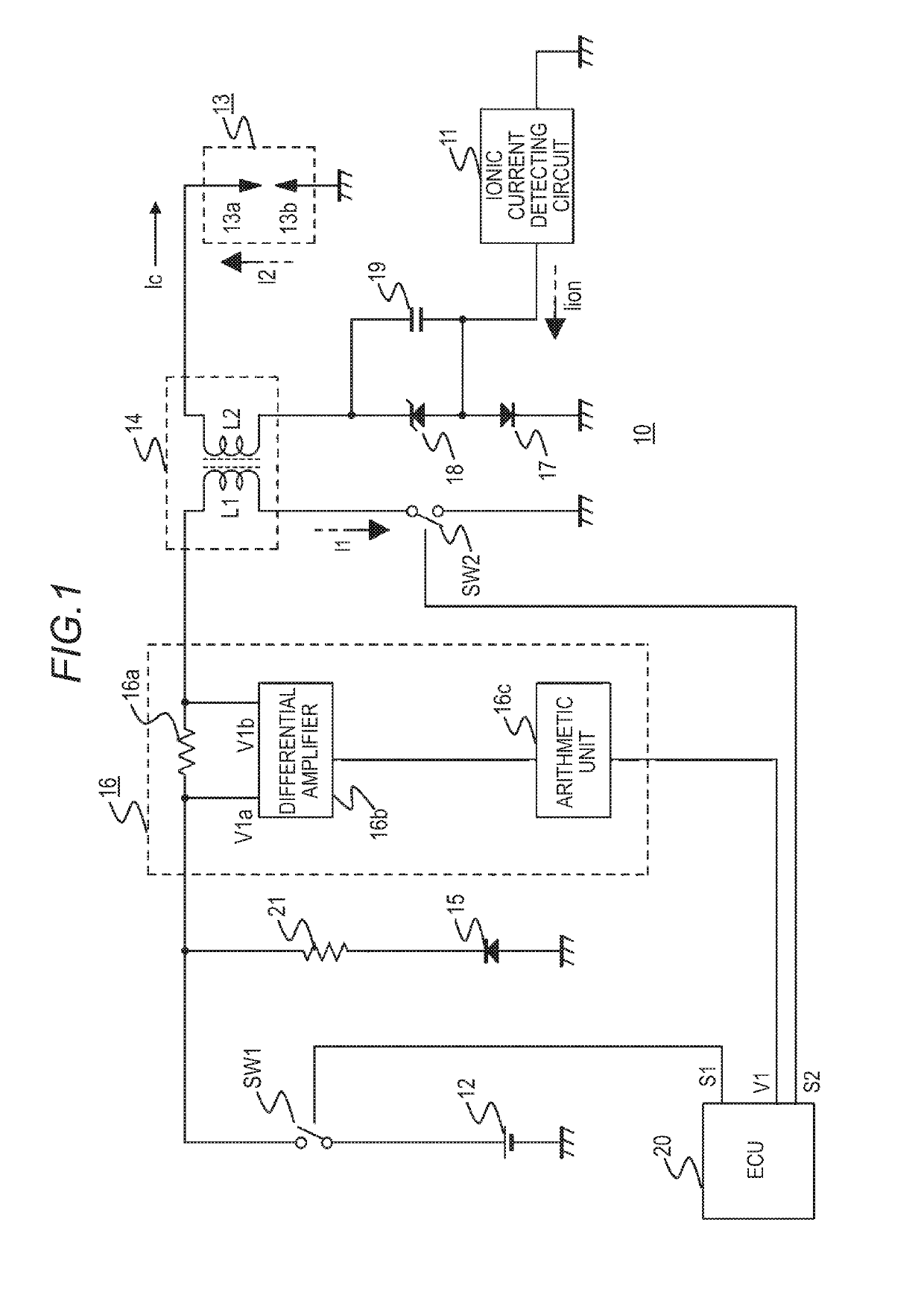
[0034]FIG. 1 is an electrical circuit diagram showing a basic configuration of an internal combustion engine combustion state detecting device according to a first embodiment of the invention. In this embodiment, a description of a single-cylinder internal combustion engine is given, but the invention is also applicable to an internal combustion engine including a multiple of cylinders. In this case, a number of ionic current detecting devices of the same basic configuration equivalent to a number of cylinders may be included, or one portion of components of a combustion state detecting device such as a reflux current control device may be common to the multiple of cylinders.

[0035]As shown in FIG. 1, an ionic current detecting device 10 according to the internal combustion engine combustion state detecting device of the first embodiment includes an ionic current detecting circuit 11 that detects an ionic current, a power supply device 12 that outputs a constant voltage, a spark plug...

second embodiment

[0070]Next, an internal combustion engine combustion state detecting device according to a second embodiment of the invention will be described.

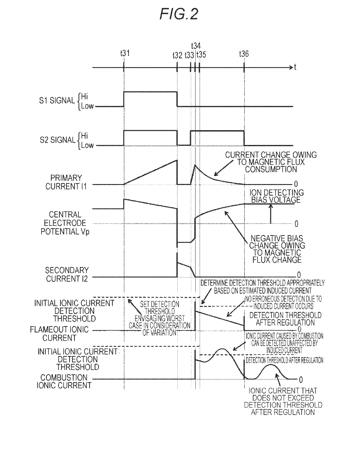
[0071]In the first embodiment, a description is given of an embodiment wherein an ionic current detection threshold is set based on an induced current at an initial stage of a discharge stopping. However, there is a tendency during a discharge stopping period for consumption of a magnetic flux to gradually slow, because of which the induced current gradually decreases, and the induced current ceases to be generated when magnetic flux in an iron core is completely consumed. Because of this, the ionic current detection threshold is in a state of being set excessively high with respect to induced current generated in a latter half of a discharge stopping operation or after a discharge stopping operation ends, and under conditions such that the number of ions generated by combustion is small and combustion is slow, such as a high EGR rate condit...

third embodiment

[0106]Next, an internal combustion engine combustion state detecting device according to a third embodiment of the invention will be described.

[0107]In the second embodiment, a description is given of an embodiment wherein the primary current I1 while a discharge is stopped is detected, and the induced current Ic generated while the discharge is stopped is estimated by carrying out a second order differentiation. However, a large amount of noise is superimposed on the primary current value that can actually be acquired, because of which carrying out a second order differentiation may be difficult in terms of numerical analysis.

[0108]In this case, it is good when the induced current Ic is estimated by the voltage generated in the primary winding L1 being detected, as partially described in the second embodiment. While magnetic flux is being consumed owing to a discharge stopping, the voltage generated in the secondary winding L2 is generated in the primary winding L1 in accordance wi...


PUM


Abstract

The invention provides an internal combustion engine combustion state detecting device such that ascertaining a combustion state using ionic current detection is carried out accurately over a wide operating range of an internal combustion engine. The internal combustion engine combustion state detecting device includes a spark plug that has a central electrode and a grounding electrode opposing across a gap, and a discharge stopping-induced current detecting device that estimates an induced current caused by a stopping of a spark discharge generated in the gap between the central electrode and the grounding electrode, wherein an ionic current detection threshold is set to a threshold value that is not affected by the induced current using the induced current estimated by the discharge stopping-induced current detecting device.

Description

BACKGROUND OF THE INVENTIONField of the Invention[0001]The present invention relates to an internal combustion engine combustion state detecting device, and more specifically, relates to an internal combustion engine combustion state detecting device such that a combustion state can be detected accurately over a wide operating range of an internal combustion engine.Description of the Related Art[0002]Operation of an internal combustion engine is such that molecules of a mixed gas inside a combustion chamber of the internal combustion engine ionize in accompaniment to combustion inside the combustion chamber, and there is a flow of a microcurrent generated when a voltage is applied via a spark plug inside the combustion chamber in an ionized state. This microcurrent is called an ionic current. It is already known that in a spark ignition type internal combustion engine, an ionic current generated inside the internal combustion engine is detected after ignition using a spark plug, an ...

Claims


Application Information

Patent Timeline
IPC IPC(8): F02P17/12F02P3/02
CPCF02P17/12F02P3/02F02P2017/125F02P2017/003F02P3/0442F02P3/053
Inventor NAKAMURA, TOSHIFUMIINADA, TAKAHIKO
Owner MITSUBISHI ELECTRIC CORP
Why Eureka
Try Eureka