Eureka AIR delivers breakthrough ideas for toughest innovation challenges, trusted by R&D personnel around the world.

Touch sensitive device and display device including the same

Active Publication Date: 2019-04-18
LG DISPLAY CO LTD
View PDF0 Cites 6 Cited by
  • Summary
  • Abstract
  • Description
  • Claims
  • Application Information

AI Technical Summary

Benefits of technology

This patent describes a touch-sensitive device that is transparent, thin, and easy to make. The device includes an electroactive layer made of a piezoelectric ceramic and an electroactive polymer bonded together. The device also has an improved driving displacement and vibration intensity compared to devices made with other materials. Additionally, a specific piezoelectric ceramics material is used to minimize accidents during manufacturing. Overall, this technology provides a better user experience for touch-sensitive devices.

Problems solved by technology

Specifically, since the haptic device of the related art is attached to a rear surface of the display panel, it is difficult to provide immediate and minute feedback on the touch of the user.
The vibration motor is configured to vibrate the entire display device, which results in several problems.
These problems include the need to increase the size of the mass body in order to increase the vibration intensity, the difficulty of frequency modulation for controlling the degree of vibration, and the slow response speed.
Further, since the eccentric rotating mass and the linear resonant actuator are formed of an opaque material, it is difficult to dispose the eccentric rotating mass and the linear resonant actuator on the display panel.
However, the shape memory alloy (SMA) has a slow response speed and a short lifespan and is formed of an opaque material.
Specifically, piezoelectric ceramics have a high piezoelectric property, but have a low durability against an external impact, so piezoelectric ceramics are easily broken by the external impact.
Further, piezoelectric ceramics are opaque and difficult to be made thin.
However, in order to be used in a mobile display device, the electroactive polymer has disadvantages including a separate process, such as a poling process or a stretching process using a high voltage, is necessary for an electronic device and a high driving voltage is necessary due to an insufficient piezoelectric property.

Method used


Image

  • Touch sensitive device and display device including the same
  • Touch sensitive device and display device including the same
  • Touch sensitive device and display device including the same

Examples


example 1

[0092]15 g of Na2CO3, 15 g of K2CO3, and 15 g of Nb2O5 were mixed in 300 mL of ion-exchanged water, and then were heat-treated for two hours using a solid state process to prepare KNN powder.

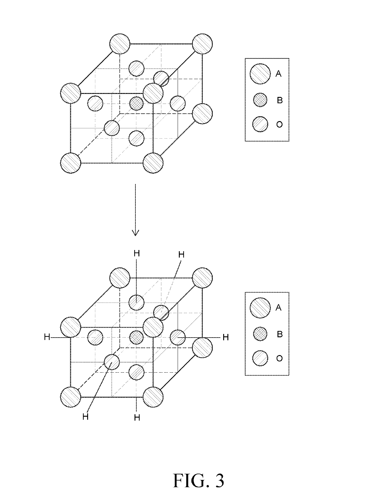
[0093]The prepared KNN powder was mixed with 400 mL of hydrogen peroxide and then heat-treated for six hours at 106° C. to form a hydroxyl group on the KNN surface.

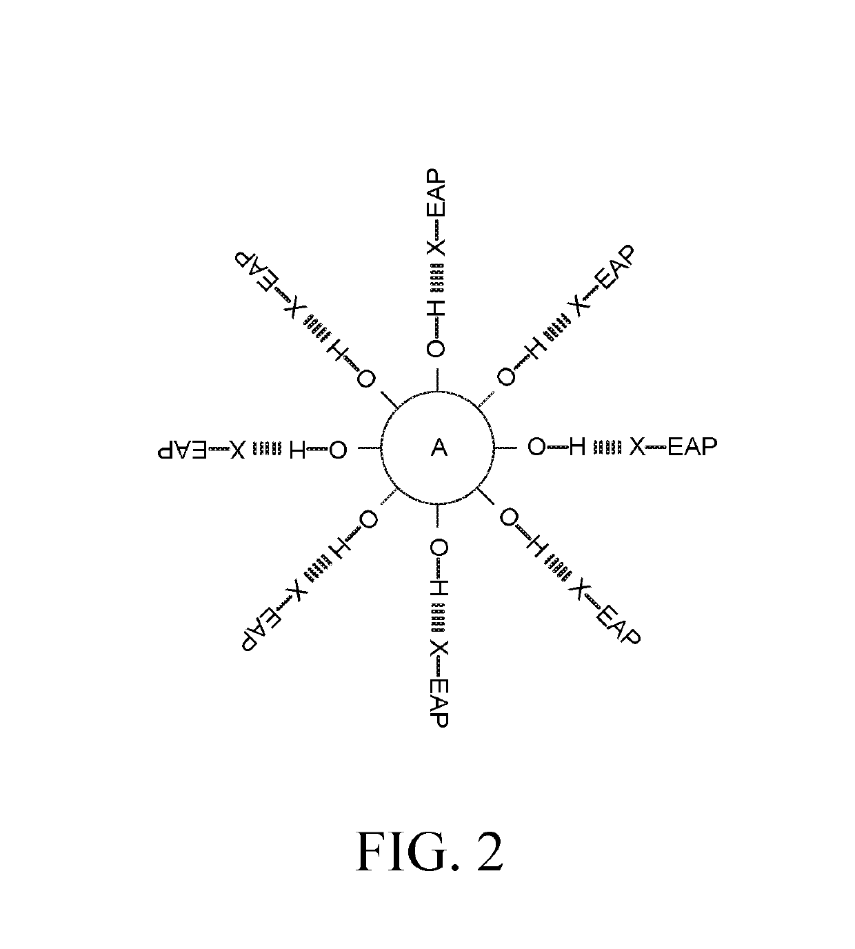
[0094]Next, 90% by weight of poly bis(trifluoroethoxy) phosphazene as polyphosphazene and 10% by weight of KNN in which the hydroxyl group was formed were mixed and then stirred to prepare an electroactive matrix in which the KNN and the polyphosphazene formed a hydrogen bond.

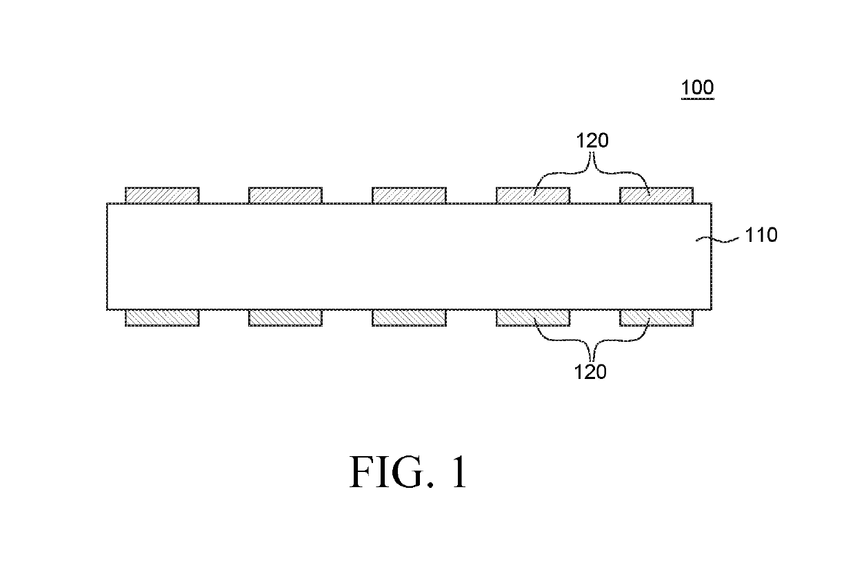
[0095]Solution casting was performed on the prepared electroactive matrix on an ITO electrode, and then the electroactive matrix was dried to obtain an electroactive active layer having a thickness of 100 μm. Thereafter, ITO was coated on an opposite surface of the prepared electroactive layer to prepare a touch sensitive device in which transparent electrodes we...

experimental example 1

Measurement of Dielectric Constant

[0099]Capacitance was measured using an LCR meter (4284A) and the following Equation 1 was used to calculate dielectric constants of touch sensitive devices prepared by Example 1 and Comparative Example 1. A measurement result is illustrated in FIG. 4.

εr=C×t / A   [Equation 1]

[0100]εr: dielectric constant, C: capacitance, t: thickness of electroactive layer, A: contact cross-sectional area of electrode)

[0101]Referring to FIG. 4, it is confirmed that the dielectric constant in Example 1 in which the piezoelectric ceramic and the electroactive polymer form the electroactive matrix through the hydrogen bond is approximately twice as high than that of Comparative Example 1 in which the piezoelectric ceramic and the electroactive polymer are simply mixed, in the entire frequency area.

[0102]Hereinafter, FT-IR analysis in FIGS. 5A and 5B was performed in order to verify whether the electroactive matrix according to an exemplary embodiment of the present disc...


PUM

PropertyMeasurementUnit
Transparencyaaaaaaaaaa
Piezoelectricityaaaaaaaaaa
Ferroelectricityaaaaaaaaaa

Abstract

Provided is a touch sensitive device including an electroactive layer formed of an electroactive matrix, wherein the electroactive matrix has a structure in which a piezoelectric ceramic and an electroactive polymer (EAP) are bonded and an electrode disposed on at least one surface of the electroactive layer. According to an exemplary embodiment of the present disclosure, the touch sensitive device uses an electroactive matrix has an excellent transparency, can be made thin, and has a high piezoelectric property so that the light transmittance and the vibration intensity of the touch sensitive device can be improved.

Description

CROSS-REFERENCE TO RELATED APPLICATIONS[0001]This application claims priority from and the benefit under 35 U.S.C. § 119(a) of Korean Patent Application No. 10-2017-0135462 filed on Oct. 18, 2017, in the Korean Intellectual Property Office, the disclosure of which is incorporated herein by reference.BACKGROUND OF THE INVENTIONField of the Invention[0002]The present disclosure relates to a touch sensitive device and a display device including the same, and more particularly to a touch sensitive device including an electroactive matrix with improved permittivity and a display device including the same.Description of the Related Art[0003]In response to recent demand from users who want to conveniently use various display devices including a liquid crystal display device and an organic light emitting display device, a touch-type display device in which a user touches a display device to input information is commonly produced. Accordingly, studies for utilizing a haptic device to provide...

Claims


Application Information

Patent Timeline
IPC IPC(8): G06F3/01G06F3/041C08G79/025
CPCG06F3/016G06F3/041C08G79/025G02F1/13338G06F3/0412G06F3/044H10N30/852G08B6/00
Inventor KIM, CHIWANKIM, TAEHEONSHIN, SUNGEUILEE, YONGWOORYU, KYUNGYEOLKHO, YUSEON
Owner LG DISPLAY CO LTD
Why Eureka
Eureka Blog
Learn More