Anisotropic nanorod-applied light-emitting diode and light-emitting device including the same

Active Publication Date: 2019-04-25
LG DISPLAY CO LTD
View PDF0 Cites 7 Cited by
  • Summary
  • Abstract
  • Description
  • Claims
  • Application Information

AI Technical Summary

Benefits of technology

[0010]Embodiment of the present disclosure are to provide a light-emitting diode having improved charge mobility by reducing charge trap sites while driving, a method of forming a charge transfer layer constituting the light-emitting diode, and a light-emitting device having t

Problems solved by technology

As described above, due to a relatively high HOMO energy level of the organic compound applied to the ETL, some of the holes injected into the EML are leaked to the ETL.
Particularly, in a QLED in which an inorganic light-emitting material having a valence band energy level deeper than the HOM

Method used


Image

  • Anisotropic nanorod-applied light-emitting diode and light-emitting device including the same
  • Anisotropic nanorod-applied light-emitting diode and light-emitting device including the same
  • Anisotropic nanorod-applied light-emitting diode and light-emitting device including the same

Examples


Example

Example 1: Manufacture of Light-Emitting Diode

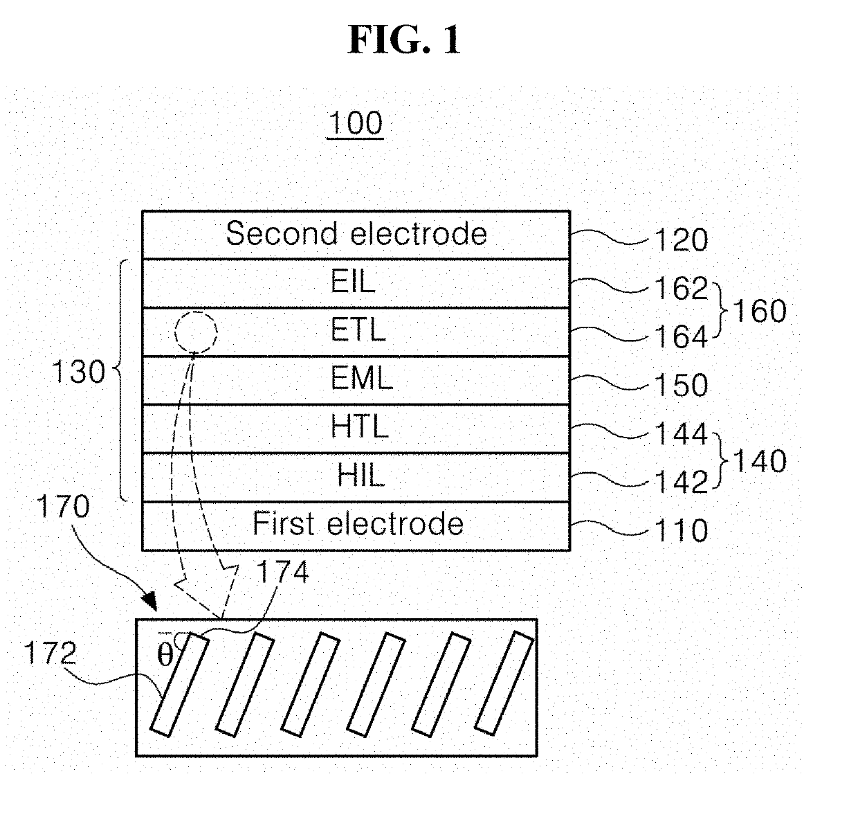
[0124]Zinc oxide (ZnO) particles having an average aspect ratio (AR) of the long axis to the short axis of 2 as anisotropic nanorod-type inorganic particles were purchased commercially and applied to an ETL of a light-emitting diode. Particularly, patterning of an ITO glass was performed to have an emission area of 3 mm×3 mm, and then washed. Subsequently, an emissive layer and a cathode were stacked according to the following order: an HIL (PEDOT:PSS, spin coating (5000 rpm) and then heating at 150° C. for 30 minutes; 30 nm), an HTL (spin coating (4000 rpm) of TFB (8 mg / mL in toluene), and then heating at 180° C. for 30 minutes; 20 nm), an EML (spin coating (3000 rpm) of InP-based red QDs (10 mg / mL in hexane) and then heating at 80° C. for 30 minutes; 20 nm), an ETL (spin coating of ZnO having an AR of 2 (12.5 mg / mL in ethanol), and then heating at 80° C. for 30 minutes; 20 nm).

[0125]The substrate on which the emissive layer is formed a...

Example

Example 2: Manufacture of Light-Emitting Diode

[0126]A light-emitting diode was manufactured in the same manner as described in Example 1, except that anisotropic nanorod (NR)-type ZnO particles having an AR of 3 as inorganic particles of an ETL were used.

Example

Example 3: Manufacture of Light-Emitting Diode

[0127]A light-emitting diode was manufactured in the same manner as described in Example 1, except that anisotropic nanorod (NR)-type ZnO particles having an AR of 4 as inorganic particles of an ETL were used.


PUM


Abstract

The present disclosure relates to a light-emitting diode including a first electrode and a second electrode facing each other; an electron transfer layer between the first electrode and the second electrode; and a light emitting material between the first electrode and the second electrode, wherein the electron transfer layer consists of anisotropic nanorods, and the long axes of the anisotropic nanorods are arranged at an angle of about 20 degrees to about 90 degrees with respect to an interface with an adjacent layer into which electrons are injected.

Description

CROSS-REFERENCE TO RELATED APPLICATIONS[0001]This application claims the priority benefit under 35 U.S.C. § 119(a) of Korean Patent Application No. 10-2017-0136359, filed in the Korean Intellectual Property Office on Oct. 20, 2017, which is incorporated herein by reference in its entirety.BACKGROUND OF THE INVENTIONField of the Invention[0002]The present disclosure relates to a light-emitting diode, and more particularly, to a light-emitting diode having improved luminescence properties and a light-emitting device including the same.Discussion of the Related Art[0003]Various flat panel display devices have been developed as it is possible for these devices to display a large amount of image data. Among flat panel display devices, an organic light-emitting diode (OLED) display device and a quantum dot light-emitting diode (QLED) display device can have a thin film structure and low power consumption, and thus, have attracted attention as next-generation display devices that replace l...

Claims


Application Information

Patent Timeline
IPC IPC(8): H01L51/50H01L51/00H01L51/56
CPCH01L51/5072H01L51/502H01L51/0007H01L51/56H01L2251/556H01L2251/5353H01L2251/5369H01L2251/303H01L27/3244H01L2251/558H01L2251/552H01L51/5004H01L33/005H01L33/145H01L33/38H10K50/00H10K50/805H10K71/00H10K59/12H10K50/115H10K50/16H10K2102/331H01L33/14H01L33/22H01L33/44H01L27/156H10K71/15H10K50/11H10K2101/30H10K2101/40H10K2102/00H10K2102/321H10K2102/351H10K2102/361
Inventor WOO, SUNG-LLKIM, DONG-YOUNGCHOI, HYE-OCK
Owner LG DISPLAY CO LTD
Why Eureka
Try Eureka