Customizable Engine Air Intake/Exhaust Systems

a technology of air intake and exhaust system, which is applied in the direction of air intake for fuel, combustion-air/fuel-air treatment, machines/engines, etc., can solve the problems of reducing the flow rate and the air charge introduced, and limited ability to reconfigure the design, so as to achieve superior engine performance and substantial engine power increase

Active Publication Date: 2019-05-02
AUTO IP LLC
View PDF0 Cites 16 Cited by
  • Summary
  • Abstract
  • Description
  • Claims
  • Application Information

AI Technical Summary

Benefits of technology

[0006]The present invention provides compact and reconfigurable automotive internal combustion engine air intake and exhaust systems suitable for use in front-engine, mid-engine and rear-engine vehicles. The systems are designed to yield superior engine performance and to permit substantial increases in engine power by exchanging and adding relatively few principal components, which themselves are designed to cooperate and permit easy substitution. The components utilized in the systems of the present invention are inter-related and capable of being attached to and disconnected with relative ease to form various air intake and exhaust gas configurations. The systems of the present invention offer at least ten different configuration options, and are particularly suitable for an internal combustion piston engine having two cylinder banks of at least two cylinders each, each bank arranged in a row and inclined from the vertical so as to form a V.

Problems solved by technology

Specifically, the path that the intake air must take to the cylinders can affect engine performance, with a lengthier and / or circuitous path reducing the flow rate and the air charge introduced into the cylinders.
In order to accommodate the various design requirements, intake and exhaust systems are often specific to a particular engine and vehicle platform, with only limited ability to reconfigure the design prior to vehicle shipment, and even less in the after-market.

Method used


Image

  • Customizable Engine Air Intake/Exhaust Systems
  • Customizable Engine Air Intake/Exhaust Systems
  • Customizable Engine Air Intake/Exhaust Systems

Examples


Embodiment Construction

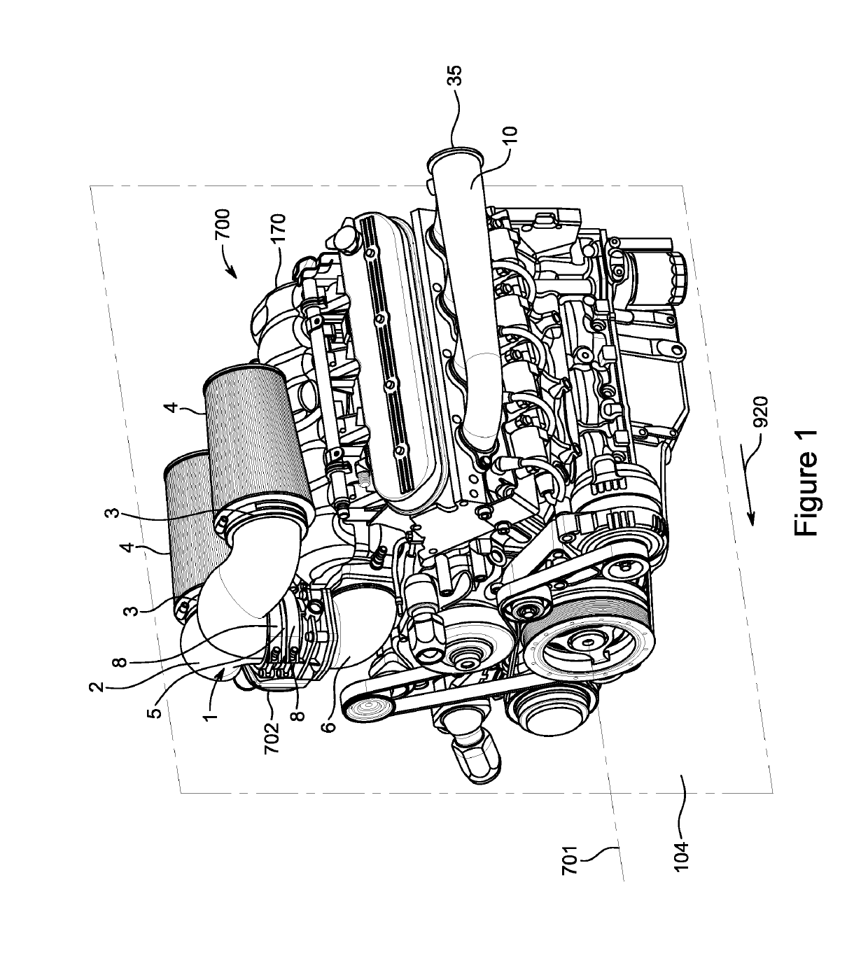
[0047]In the embodiment of the present invention depicted in FIG. 1, there is shown an eight cylinder V-8 engine 700. The “forward” portion or “front” of engine 700, and like references, refers to those portions of engine 700 most closely oriented to the head of the arrow 920, shown in FIG. 1; for the engine of the preferred embodiment, the belt-driven accessories are located at the front of engine 700. The “rearward” portion or “rear” of engine 700, and like references, refers to those portions of engine 700 least closely oriented to the head of the arrow 920; for the engine of the preferred embodiment, the drive shaft will exit at the rear of engine 700. Correspondingly, the “left” side of the engine is that side which is generally visible in FIG. 1, whereas the “right” side of the engine generally is not visible in FIG. 1.

[0048]In similar manner, references in this disclosure to the “forward” or “front” portion of any component or assemblage, and like references, refers to the po...


PUM


Abstract

A multi-stage reconfigurable air intake and exhaust system for an internal combustion piston engine having a first row of at least two cylinders inclined relative to a vertical plane, a second row of at least two cylinders inclined relative to the vertical plane, and the two rows of cylinders form a V configuration with the vertical plane being approximately equidistant between the two rows. The system comprises a Stage 1 package and a Stage 2 package. The Stage 1 package includes a first exhaust manifold adapted to be secured to the first row of cylinders for receiving and collecting in a plenum exhaust gases from the first row of cylinders, where the first exhaust manifold includes a first exhaust gas discharge aperture for discharging exhaust gases, the first exhaust gas discharge aperture is located at a first fixed spatial position when the first exhaust manifold is secured to the first row of cylinders, and there is provided first connecting means proximate the first exhaust gas aperture. The Stage 1 package additionally includes a second exhaust manifold adapted to be secured to the second row of cylinders for receiving and collecting in a plenum exhaust gases from the second row of cylinders, where the second exhaust manifold includes a second exhaust gas discharge aperture for discharging exhaust gases, the second exhaust gas discharge aperture is located at a second fixed spatial position when the second exhaust manifold is secured to the first row of cylinders, and there is provided second connecting means proximate the second exhaust gas aperture. The Stage 2 package includes a first turbo exhaust manifold adapted to be secured to the first row of cylinders for receiving and collecting in a plenum exhaust gases from at least from the first row of cylinders, where the first turbo exhaust manifold includes a first turbocharger connection aperture adapted for mounting a turbocharger and for delivering to the turbocharger exhaust gases from either the first row of cylinders or the first row of cylinders and the second row of cylinders, a first exhaust gas passage aperture and third connecting means proximate the first exhaust gas passage aperture, the first turbo exhaust manifold being dimensioned so that the first exhaust gas passage aperture is located at about the first fixed spatial position when the first turbo exhaust manifold is secured to the first row of cylinders in lieu of the first exhaust manifold, and a crossover pipe assembly having a second exhaust gas passage aperture and fourth connecting means proximate the second exhaust gas passage aperture, and having a third exhaust gas passage aperture and fifth connecting means proximate the third exhaust gas passage aperture, where the fourth and fifth connecting means are each adapted for coupling to any two of the first, second and third connecting means

Description

CROSS-REFERENCES TO RELATED APPLICATIONS[0001]This application claims the benefit of U.S. Provisional Application No. 62 / 577,423, filed Oct. 26, 2017, U.S. Provisional Application No. 62 / 577,965, filed Oct. 27, 2017, U.S. Provisional Application No. 62 / 598,045, filed Dec. 13, 2017, U.S. Provisional Application No. 62 / 616,601, filed Jan. 12, 2018, U.S. Provisional Application No. 62 / 678,460, filed May 31, 2018, U.S. Provisional Application No. 62 / 687,461, filed Jun. 20, 2018, and U.S. Provisional Application No. 62 / 697,072, filed Jul. 12, 2018.BACKGROUND OF THE INVENTIONField of the Invention[0002]This invention relates to the air intake and exhaust systems for internal combustion engines.Description of the Related Art[0003]When reciprocating internal combustion engines draw intake air from the atmosphere into the cylinders, the air often passes through various connecting passageways, such as pipes and chambers. In some cases, where increased power and / or thermal efficiency is desire...

Claims


Application Information

Patent Timeline
Patent Type & Authority Applications(United States)
IPC IPC(8): F02M35/10F02M35/104F01N13/10
CPCF02M35/10091F02M35/10242F02M35/104F01N13/10F01N2340/04F01N2340/06F02M2700/05F01N13/107F01N2340/02F01N2450/24F01N2470/14F01N2470/16
Inventor TIRAMANI, PAOLODENMAN, KYLE
Owner AUTO IP LLC
Why Eureka
Try Eureka