Solar power generation unit using optical fibers and power generation system implementing the unit

a technology of optical fiber and solar power generation system, applied in the direction of optical fibre, fibre light guide, instruments, etc., can solve the problems of large installation area, high-purity crystalline silicon-based solar panels, and low photoelectric transformation efficiency of solar power generation systems, so as to reduce mobility, installation area, and capacity. , the effect of increasing maintenance expenses

Inactive Publication Date: 2019-05-02
BAE SEOK MAN +1
View PDF4 Cites 4 Cited by
  • Summary
  • Abstract
  • Description
  • Claims
  • Application Information

AI Technical Summary

Benefits of technology

[0023]According to one or more embodiments, a solar power plant and small- and medium-sized power generation systems with significantly reduced mobility, expenses, and installation areas, as well as high capacity, may be publicly provided. In particular, environmental destruction that is caused to provide a large area for installation of previous solar power plants, and the increase in maintenance expenses due to a decreased lifespan due to changes in the surrounding environment may be innovatively improved. In particular, there is a wide range of fields of application, including in household solar power electricity, solar power generation in a region in which it is difficult to obtain a site, space engineering, a large vessel, electric cars, portable electric products, etc.

Problems solved by technology

A solar power generation system does not have high photoelectric transformation efficiency, and thus, for high-capacity power generation, a very large installation area is required.
Currently, a high-purity crystalline silicon-based solar panel, which is generally used for solar power generation, absorbs about 90% of the wavelength range of 500 to 800 nm, and has low efficiency or little absorption with respect to other wavelengths.
A solar power generation facility mounted on a rooftop of a building or on the ground mainly uses the direct-type, but the direct-type has a lower efficiency than the condensing-type using a lens or a mirror.
Thus, these previous solar panels require a high manufacturing cost, and reduction of the lifespan thereof due to high concentration of light is inevitable.

Method used


Image

  • Solar power generation unit using optical fibers and power generation system implementing the unit
  • Solar power generation unit using optical fibers and power generation system implementing the unit
  • Solar power generation unit using optical fibers and power generation system implementing the unit

Examples


Embodiment Construction

Technical Problem

[0005]Provided are a solar power generation unit capable of significantly reducing an occupied area and greatly increasing power generation efficiency; and a power generation system implementing the solar power generation unit.

[0006]Provided are a solar power generation unit having a low manufacturing cost and reduced installation expenses; and a solar power generation system implementing the solar power generation unit.

[0007]Provided are a solar power generation unit capable of effectively protecting a solar panel from thermal shocks and increasing the lifespan of the solar panel; and a solar power generation system implementing the solar power generation unit.

Solution to Problem

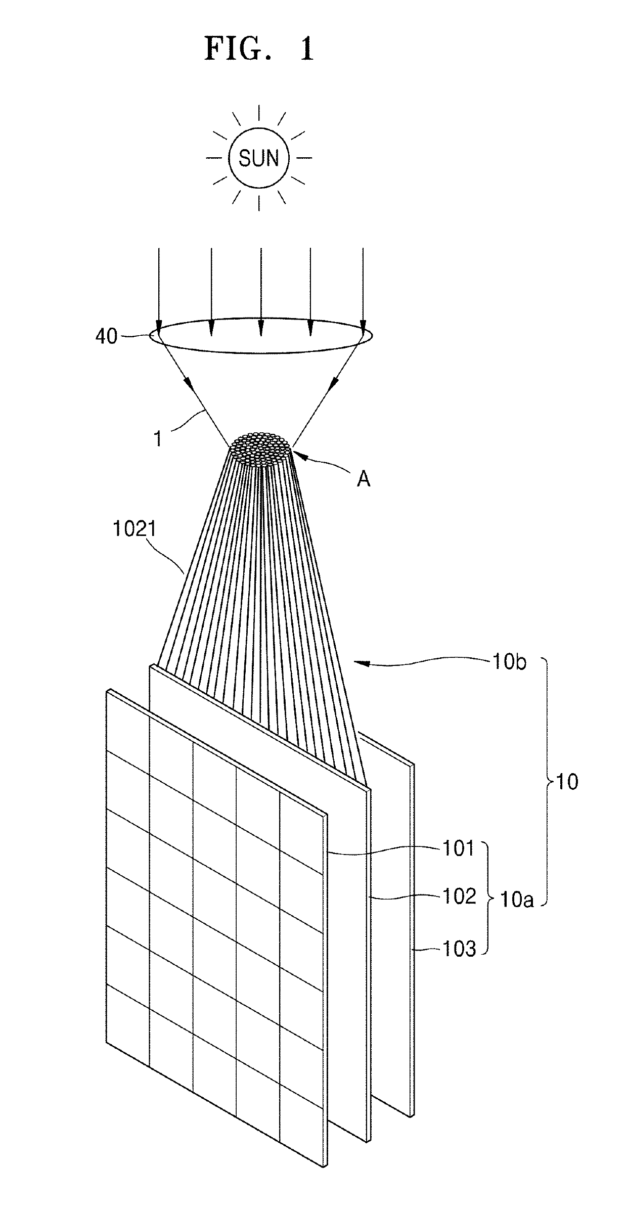
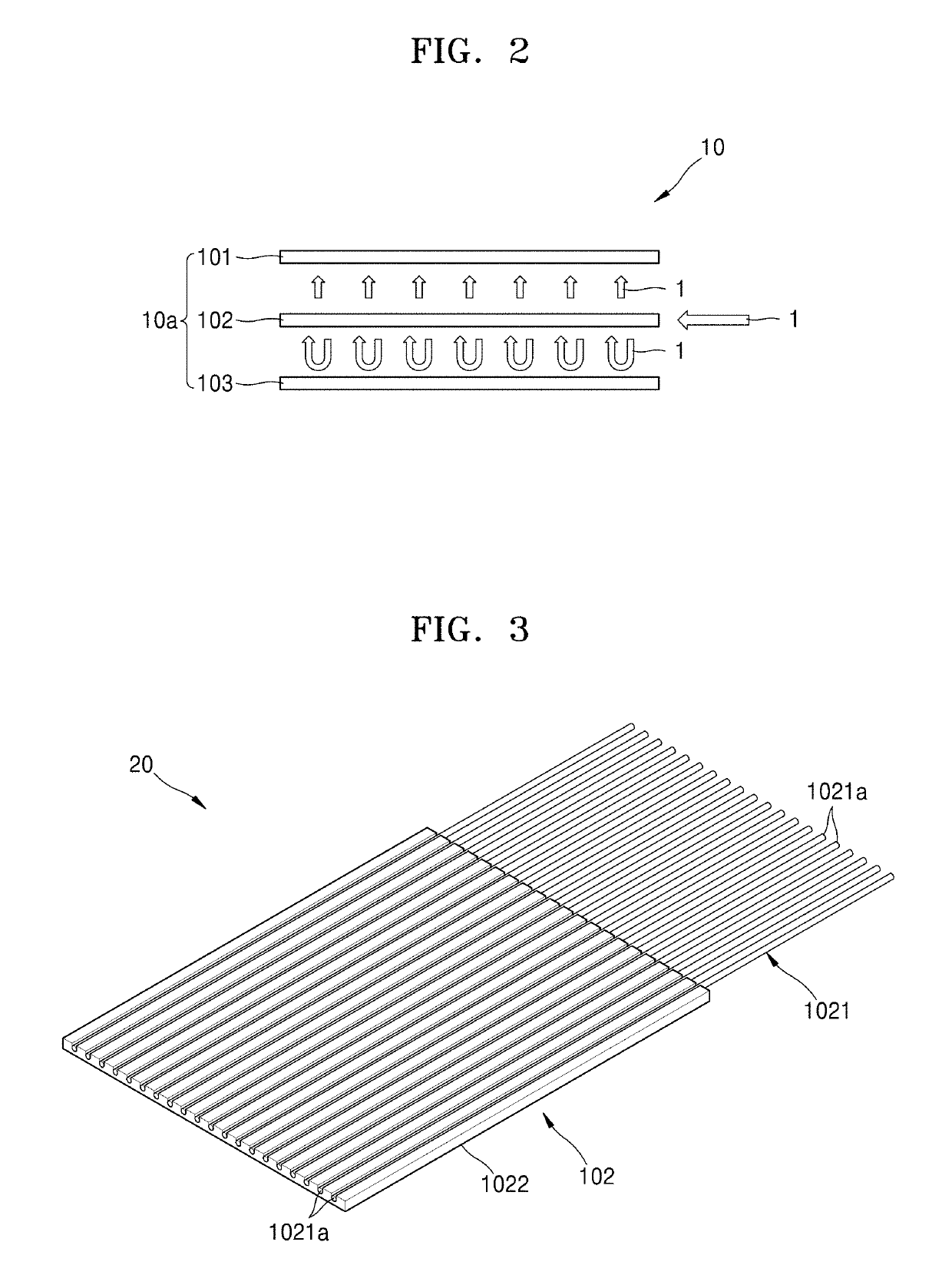
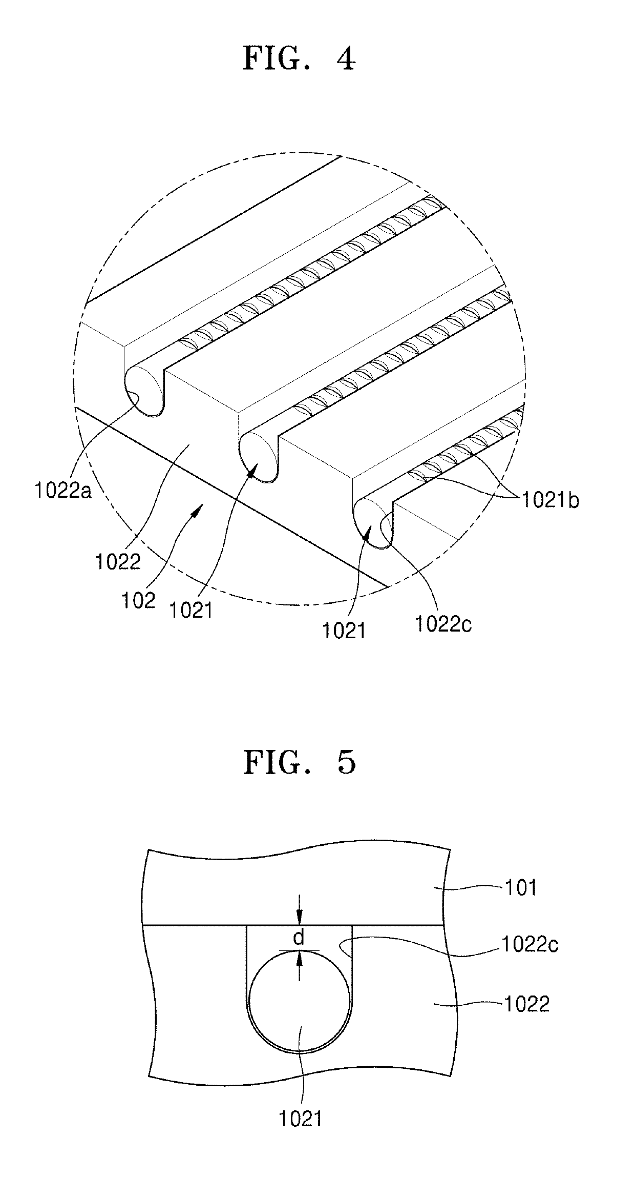
[0008]According to an aspect of the present disclosure, a solar power generation unit includes: a transporter configured to transport light waves from the sun through a plurality of optical fibers; and a power generator configured to generate electricity by using the light waves incident to...


PUM


Abstract

Provided is a solar power generation unit including: a transporter configured to transport light waves from the sun through a plurality of optical fibers; and a power generator configured to generate electricity by using the light waves incident to the plurality of optical fibers from the transporter, the power generator including a light wave guide configured to arrange the plurality of optical fibers on a plane or a sheet to face a light-incident surface of a solar panel, wherein a plurality of windows are formed in an outer circumferential surface of the plurality of optical fibers, the plurality of windows being configured to refract the light waves progressing therethrough such that the light waves are forwarded to the solar panel.

Description

TECHNICAL FIELD[0001]One or more embodiments relate to a solar power generation unit using optical fibers and a power generation system implementing the solar power generation unit, and more particularly, to a solar power generation unit using a plastic optical fiber (POF) array sheet and a solar cell corresponding to the POF array sheet, and a power generation system implementing the solar power generation unit.BACKGROUND ART[0002]Solar power generation using sunlight, which is a limitless energy source, uses a panel or a sheet, in which a plurality of solar cells are provided in a structure to which the sunlight having high energy is incident. A solar power generation system does not have high photoelectric transformation efficiency, and thus, for high-capacity power generation, a very large installation area is required.[0003]Sunlight has a very wide wavelength range, which includes a visible light region of 400 to 700 nm. Sunlight has varying intensities based on the wavelength ...

Claims


Application Information

Patent Timeline
Patent Type & Authority Applications(United States)
IPC IPC(8): H02S40/22G02B6/42G02B19/00G02B6/36
CPCH02S40/22G02B6/4214G02B19/0042G02B6/3664G02B6/3608G02B6/3636G02B6/001H02S40/425Y02E10/52H01L31/0543H01L31/0547G02B6/06G02B6/0065G02B6/02395
Inventor BAE, SEOK MAN
Owner BAE SEOK MAN
Why Eureka
Try Eureka