
Apparatus for generating electrical energy based on hydrophilic fiber membrane and method of fabricating same

a technology of hydrophilic fiber membrane and apparatus, which is applied in the direction of generator/motor, electrolytic capacitor, membrane, etc., can solve the problems that the high-frequency ac electrical energy generated as described above cannot be directly connected to the anelectronic, piezoelectric or triboelectric energy generation apparatus, and achieves the effect of maintaining charge neutrality

Active Publication Date: 2019-05-16
KOREA ADVANCED INST OF SCI & TECH
View PDF0 Cites 4 Cited by
  • Summary
  • Abstract
  • Description
  • Claims
  • Application Information

AI Technical Summary

Benefits of technology

The present invention provides an apparatus for generating DC energy through the asymmetrical wetting of a polar solvent with respect to a hydrophilic membrane coated with conductive carbon particles. The apparatus is designed to continuously generate energy using a simple polar solvent, such as water, and is suitable for providing power to electronic devices and energy storage devices. The apparatus is easy to fabricate and can be mass-produced and large-area fabricated using a simple dipping process. The technical effects of this invention include the provision of a simple, efficient, and scalable apparatus for generating clean and reliable electrical energy using a simple polar solvent and a hydrophilic fiber membrane coated with a carbon layer.

Problems solved by technology

However, the developed electrical energy generation apparatus has some clear disadvantages.
AC electrical energy of a high frequency generated as described above cannot be directly connected to anelectronic device to drive the electronic device.
For this reason, the piezoelectric or triboelectric energy generation apparatus has a disadvantage in that generated energy can be used only when a separate rectifier circuit and energy storage device are always involved.
Another problem is that generation efficiency of the electrical energy generation apparatus continues to decrease because repetitive mechanical deformation, friction and a thermal flow damage a device.
The reason for this is that the continuous mechanical deformation, friction and thermal flow inevitably damages or deforms the core material and substance of the electrical energy generation apparatus.
The deformation of a device attributable to mechanical deformation, friction and / or a thermal flow is a main cause that an energy generation material is delaminated from a current collector, so energy generation efficiency is deteriorated and device reliability is decreased.

Method used


Image

  • Apparatus for generating electrical energy based on hydrophilic fiber membrane and method of fabricating same
  • Apparatus for generating electrical energy based on hydrophilic fiber membrane and method of fabricating same
  • Apparatus for generating electrical energy based on hydrophilic fiber membrane and method of fabricating same

Examples


embodiment 1

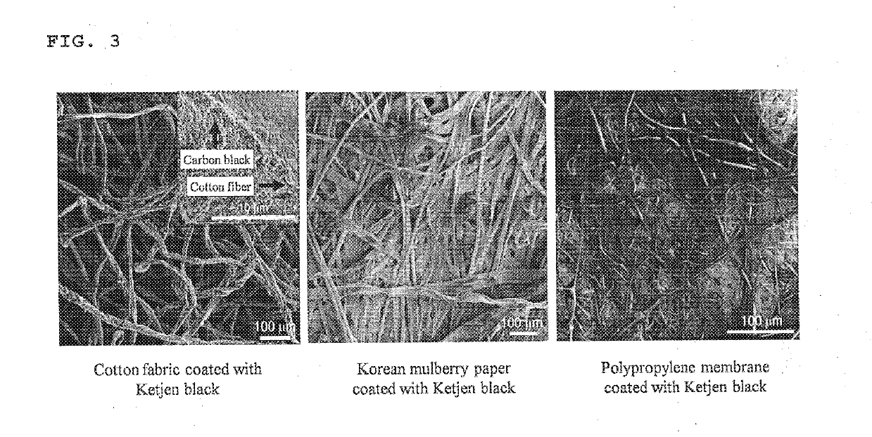
of Electrical Energy Generation Apparatuses Based on Cotton Fabric, Korean Mulberry Paper and Polypropylene Membrane Coated With Ketjen Black Using Dipping Process

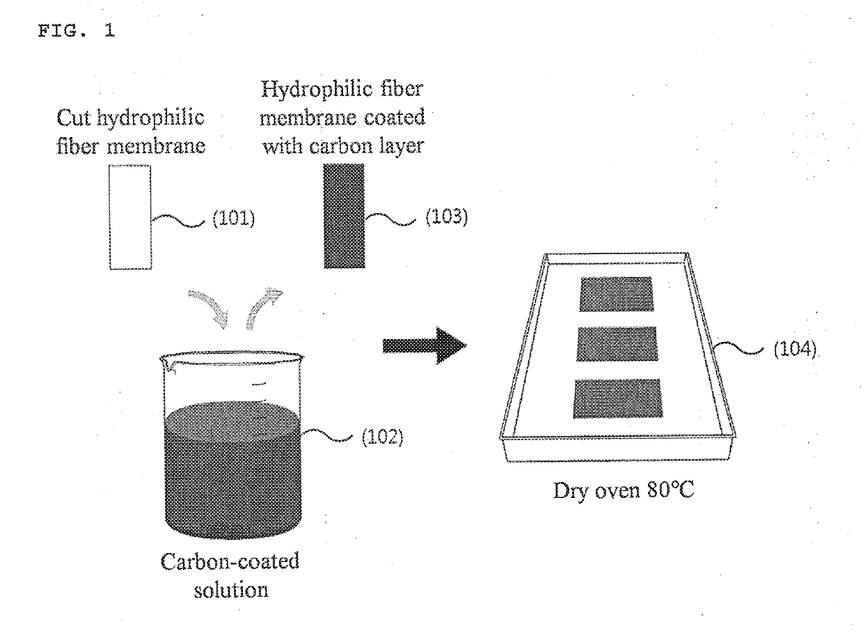
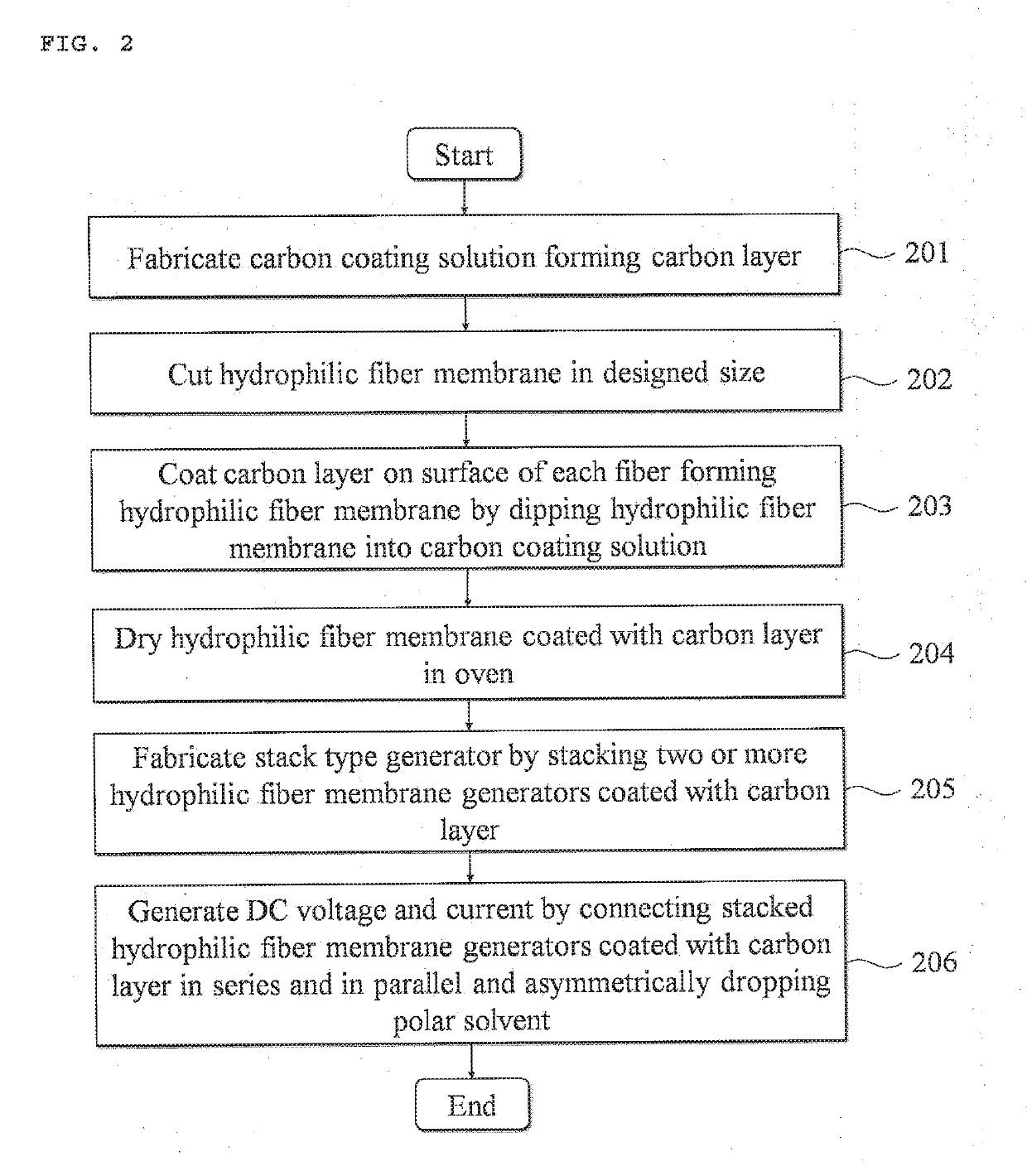
[0083]In order to fabricate a Ketjen black coating solution, Ketjen black 0.2 g and a surfactant (sodium dodecylbenzenesulfonate (SDBS)) 0.05 g were mixed with deionized water of 20 ml. A solution in which Ketjen black was dispersed was fabricated by uniformly mixing and dispersing the mixed Ketjen black solution through an ultrasonication process. For example, cotton fabric, Korean mulberry paper, a polypropylene membrane, oxygen plasma-processed non-woven fabric, hydrophilic surface-processed textile or a nanofiber may be selected as the hydrophilic fiber membrane. In the present embodiment, the hydrophilic fiber membrane was cut based on an aspect ratio 3 according to the standard of 3 cm (length)×9 cm (breadth). Each of the cut membranes was dipped into the solution in which the carbon particles were dispersed once. Th...

embodiment 2

of Electrical Energy Generation Apparatus Coated Based on Cotton Fabric With Graphene Oxide (GO) and Carbon Nanotubes (CNTs) Using Dipping Process

[0096]In order to fabricate a GO coating solution, GO 0.2 g and a surfactant (sodium dodecylbenzenesulfonate (SDBS)) 0.05 g were mixed with deionized water of 20 ml. A GO coating solution was fabricated by uniformly mixing and dispersing the mixed GO solution through sonication. Cotton fabric was cut in a standard of 3 cm (length)×9 cm (breadth) and dipped into a solution in which GO was dispersed once. The cotton fabric coated with the dipped GO was placed on a flat tray. A cotton membrane electrical energy generation apparatus coated with GO was finally fabricated through a dry process in a dry oven of 80° C.

[0097]In order to fabricate a CNTs coating solution, CNTs 0.2 g and a surfactant (sodium dodecylbenzenesulfonate (SDBS)) 0.05 g were mixed with deionized water of 20 ml. A CNTs coating solution was fabricated by uniformly mixing and ...

embodiment 3

D Using Electrical Energy Generation Apparatus Based on Cotton Fabric Coated With Ketjen Black

[0103]FIG. 16 shows an actual shape of an electrical energy generation apparatus based on cotton fabric coated with Ketjen black. The fabricated electrical energy generation apparatus based on cotton fabric coated with Ketjen black was fabricated in the standard of 3 cm (length)×9 cm (breadth) size corresponding to the aspect ratio 3 in which water is effectively adsorbed and an asymmetrical wetting state can be well maintained. The thickness of cotton fabric used was a range of 10 μm˜1 mm. Furthermore, the electrical energy generation apparatus based on cotton fabric coated with Ketjen black may be used as a stack structure. The stacking is possible up to at least two layers to a maximum of 200 layers. There is no limit to a specific stacking thickness. The greatest advantage of the stacking is that energy density can be easily increased. In particular, a marginal space capable of further ...


PUM

PropertyMeasurementUnit
Fractionaaaaaaaaaa
Fractionaaaaaaaaaa
Thicknessaaaaaaaaaa

Abstract

Disclosed herein is a complex generator including a hydrophilic fiber membrane coated with an adsorption material. Electrical energy is generated in such a manner that the adsorption material is adsorbed onto a polar solvent in some region of the hydrophilic fiber membrane by asymmetrical wetting of the polar solvent for the hydrophilic fiber membrane.

Description

CROSS REFERENCE TO RELATED APPLICATION[0001]The present application claims the benefit of Korean Patent Application No. 10-2017-0150695 filed in the Korean intellectual Property Office on Nov. 13, 2017, Korean Patent Application No. 10-2018-0081431 filed in the Korean Intellectual Property Office on Jul. 13, 2018, Korean Patent Application No. 10-2018-0081432 filed in the Korean Intellectual Property Office on Jul. 13, 2018, Korean Patent Application No. 10-2018-0122573 filed in the Korean Intellectual Property Office on Oct. 15, 2018, and Korean Patent Application No. 10-2018-0122649 filed in the Korean Intellectual. Property Office on Oct. 15, 2018, the entire contents of which are incorporated herein by reference.BACKGROUND OF THE INVENTION1. Technical Field[0002]The present invention relates to a new concept electrical energy generation apparatus and a method of fabricating the same, wherein continuous electrical energy is generated based on an open-circuit voltage and short-cir...

Claims


Application Information

Patent Timeline
IPC IPC(8): H01G11/52H01G11/04H01G11/60H01G11/56H01G11/84
CPCH01G11/52H01G11/04H01G11/60H01G11/56H01G11/84B01D67/0046B01D67/0079B01D69/02B01D69/06B01D69/10B01D71/021B01D71/72B01D71/82H02N11/002B01D2325/26Y02E60/13B01D67/00791B01D69/1071B01D71/0211B01D71/281Y02E60/00B01D67/00793B01D71/0212
Inventor KIM, IL-DOOYUN, TAE-GWANGBAE, JIN GOOK
Owner KOREA ADVANCED INST OF SCI & TECH
Learn More