
High-brightness laser produced plasma source and methods for generating radiation and mitigating debris

a laser produced plasma and laser technology, applied in the direction of x-ray tubes, electric discharge tubes, x-ray apparatuses, etc., can solve the problems of high production cost, defect appearance on printed chips, and insufficient mask inspection, so as to reduce operating costs, reduce the level of debris, and increase the lifetime

Active Publication Date: 2019-05-30
ISTEQ BV
View PDF0 Cites 9 Cited by
  • Summary
  • Abstract
  • Description
  • Claims
  • Application Information

AI Technical Summary

Benefits of technology

The invention creates a brighter light source with less debris, which means it lasts longer and runs at lower costs.

Problems solved by technology

The general trend in lithographic production is a shift from IC inspection, which is extremely time-consuming and costly in large-scale production, to the analysis of lithographic masks.
In the case of mask defects they are projected onto a silicon substrate with a photoresist, resulting in the appearance of defects on the printed chips.
Therefore, their usage for mask inspection is inadequate due to the excessive complexity and cost.
This results in sufficiently strong erosion and means the sleeve requires frequent periodic replacement.
The disadvantages of this method include insufficiently high efficiency of the plasma-forming target material and the high cost of xenon which requires a complex system for its recirculation.
However, these devices and the method have a number of disadvantages, which include the non-reproducibility of the profile of the solid surface of the target from pulse to pulse during long-term continuous operation of the device, which affects the stability of the output characteristics of the short-wavelength radiation source.
The complexity of the design is another disadvantage, since complex movements of the target assembly and its periodic replacement are required.
During production of EUV radiation, debris particles are produced as a by-product, which can degrade the optics surface.
The level of debris produced in this source is too high and that severely limits the possibilities of its application.

Method used


Image

  • High-brightness laser produced plasma source and methods for generating radiation and mitigating debris
  • High-brightness laser produced plasma source and methods for generating radiation and mitigating debris
  • High-brightness laser produced plasma source and methods for generating radiation and mitigating debris

Examples


Embodiment Construction

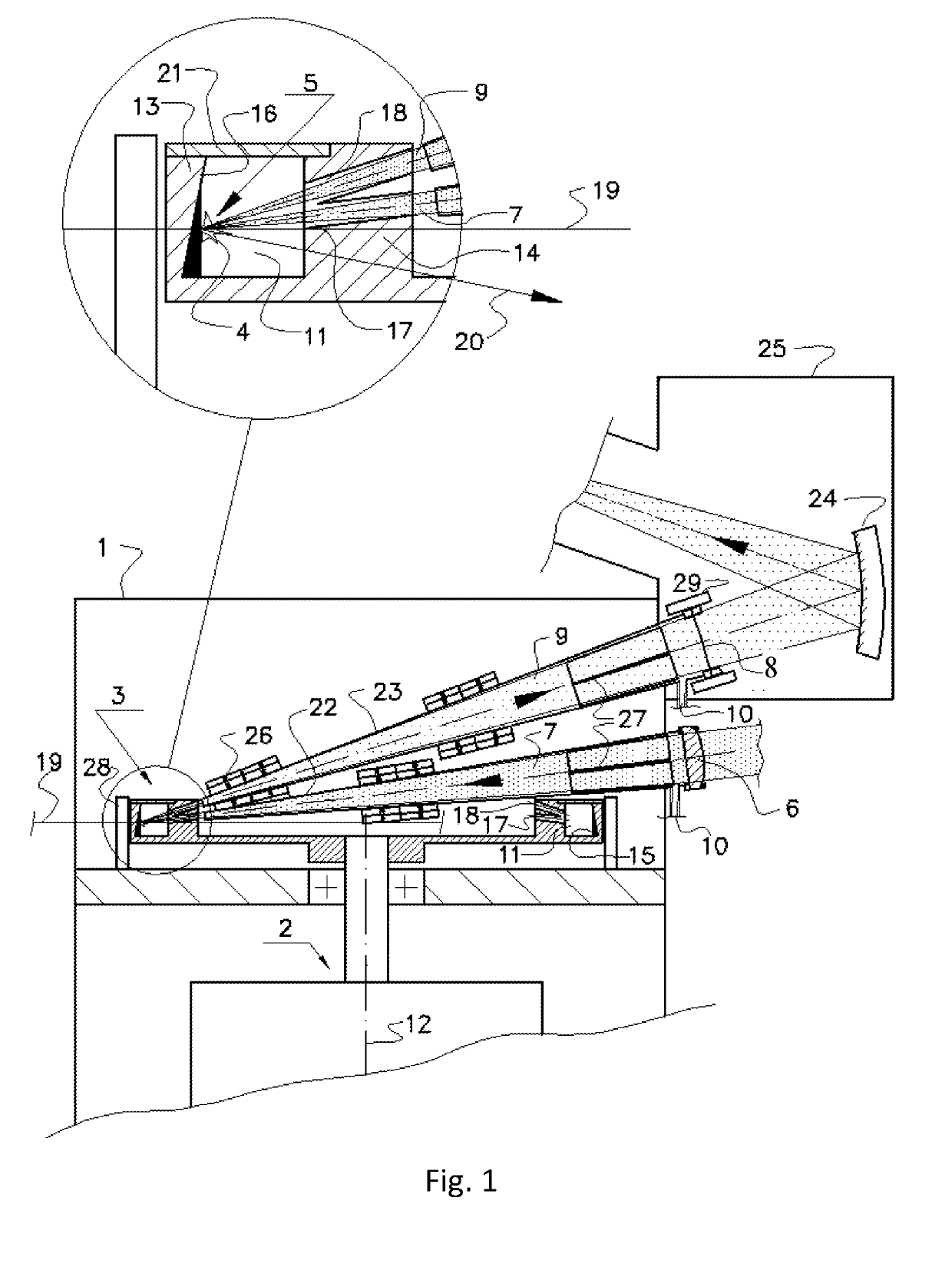
[0042]According to the embodiment of the invention schematically shown in FIG. 1, an apparatus for generating short-wavelength radiation from laser-produced plasma LPP comprises: vacuum chamber 1 containing a rotating target assembly 3 which supplies a target 4 to an interaction zone 5, an input window 6 for a pulsed laser beam 7 focused into the interaction zone, an output window 8 for an exit of the short-wavelength radiation beam 9, and gas inlets 10.

[0043]The rotating target assembly 3 has an annular groove 11 with a distal wall 13 and a proximal wall 14 relative to the axis of rotation 12.

[0044]The plasma-forming target material 15 is a molten metal located inside the annular groove 11, and the target 4 is a layer of said molten metal formed by a centrifugal force on a surface 16 of the distal wall 13 of the annular groove 11.

[0045]The proximal wall 14 of the annular groove 11 is designed to provide a line of sight between the interaction zone 5 and both the input and output wi...


PUM


Abstract

High-brightness LPP source and method for generating short-wavelength radiation which include a vacuum chamber (1) with an input window (6) for a laser beam (7) focused into the interaction zone (5), an output window (8) for the exit of the short-wavelength radiation beam (9); the rotating target assembly (3), having an annular groove (11); the target (4) as a layer of a molten metal formed by centrifugal force on the surface of the distal wall (13) of the annular groove (11) while the proximal wall (14) of the annular groove is designed to provide a line of sight between the interaction zone and both the input and output windows particularly during laser pulses. A method for mitigating debris particles comprises using an target orbital velocity high enough for the droplet fractions of the debris particles exiting the rotating target assembly not to be directed towards the input and output windows.

Description

CROSS-REFERENCE TO RELATED APPLICATIONS[0001]Current patent application claims priority to the Russian patent application No. 2017141042 filed on Nov. 24, 2017.FIELD OF INVENTION[0002]The invention relates to a high-brightness radiation source for generating short-wavelength radiation including x-ray, extreme ultraviolet or vacuum ultraviolet, but mainly in the field of extreme ultraviolet EUV at a wavelength of 13.5 nm and to methods for both generating radiation from high-temperature laser produced plasma (LPP) and mitigating debris. The scope of applications includes various types of inspection such as actinic EUV mask inspection at the working wavelength of the lithographic process.BACKGROUND OF INVENTION[0003]The new generation projection lithography for large-scale production of integrated circuits IC with structure sizes of 10 nm or less is based on the use of EUV radiation in the range of 13.5+ / −0.135 nm corresponding to effective reflection of multilayer Mo / Si mirrors. The ...

Claims


Application Information

Patent Timeline
IPC IPC(8): H05G2/00
CPCH05G2/006H05G2/005H05G2/008H01J35/00
Inventor VINOKHODOV, ALEKSANDR YURIEVICHIVANOV, VLADIMIR VITALIEVICHKOSHELEV, KONSTANTIN NIKOLAEVICHKRYVOKORYTOV, MIKHAIL SERGEYEVICHKRIVTSUN, VLADIMIR MIKHAILOVICHLASH, ALEKSANDR ANDREEVICHMEDVEDEV, VYACHESLAV VALERIEVICHSIDELNIKOV, YURY VIKTOROVICHYAKUSHEV, OLEG FELIKSOVICH
Owner ISTEQ BV
Learn More