Supervision device for ambulatory infusion

a technology of ambulatory infusion and supervising device, which is applied in the direction of other medical devices, process and machine control, instruments, etc., can solve the problems of insufficient thermal coupling, difficult to achieve good thermal coupling e.g. with tubing walls, and at least partly insufficient thermal coupling, so as to enhance the thermal coupling between thermoelectric elements and increase the thermal insulation

Active Publication Date: 2019-06-13
ROCHE DIABETES CARE INC
View PDF4 Cites 10 Cited by
  • Summary
  • Abstract
  • Description
  • Claims
  • Application Information

AI Technical Summary

Benefits of technology

[0073]Providing the upstream thermoelectric element and the downstream thermoelectric element on different carriers with a gap in between is counter-intuitive in so far as the gap adds to the distance between the thermoelectric elements along the flow channel, which is generally unfavorable. A common carrier, e.g. a common printed circuit board, however, forms a thermal bridge between the thermoelectric elements, resulting in a considerable portion of the heat transfer between the thermoelectric elements occurring via the carrier, rather than the flow channel respectively the liquid within the flow channel, as desired. A gap between the thermoelectric elements, in contrast, increases the thermal insulation because of the low thermal conductivity of the (air) gap, thus enhancing the thermal coupling between thermoelectric elements and flow channel. This favorable effect is found to outweigh the generally negative influence of the increased distance.

Problems solved by technology

For a number of reasons related to handling, manufacture and in particular costs, however, such approach is undesirable and largely unfeasible.
When providing the heating element and the temperature sensors as part of the ambulatory infusion device with a releasable coupling to a flow channel, e.g. a piece of tubing, however, a good thermal coupling e.g. with the tubing walls is hard to achieve.
Due to the very limited space in ambulatory infusion devices, however, some amount of curvature or bending is typically present in the tubing, resulting in an at least partly insufficient thermal coupling.
Small flow rates respectively an administration of small liquid drug amounts is therefore impossible to supervise.

Method used


Image

  • Supervision device for ambulatory infusion
  • Supervision device for ambulatory infusion
  • Supervision device for ambulatory infusion

Examples


Embodiment Construction

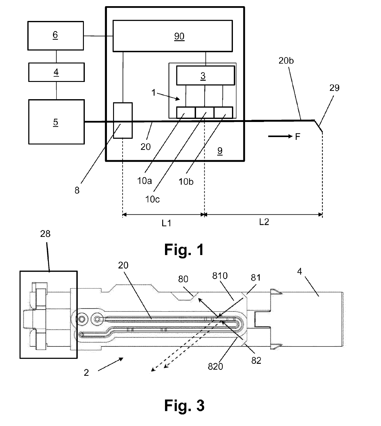
[0111]In the following, reference is first made to FIG. 1, showing an exemplary embodiment of a supervision device 9 in accordance with the present disclosure in a schematic view. The supervision device 9 includes an optical gas detector 8 and a thermal flow detector 1.

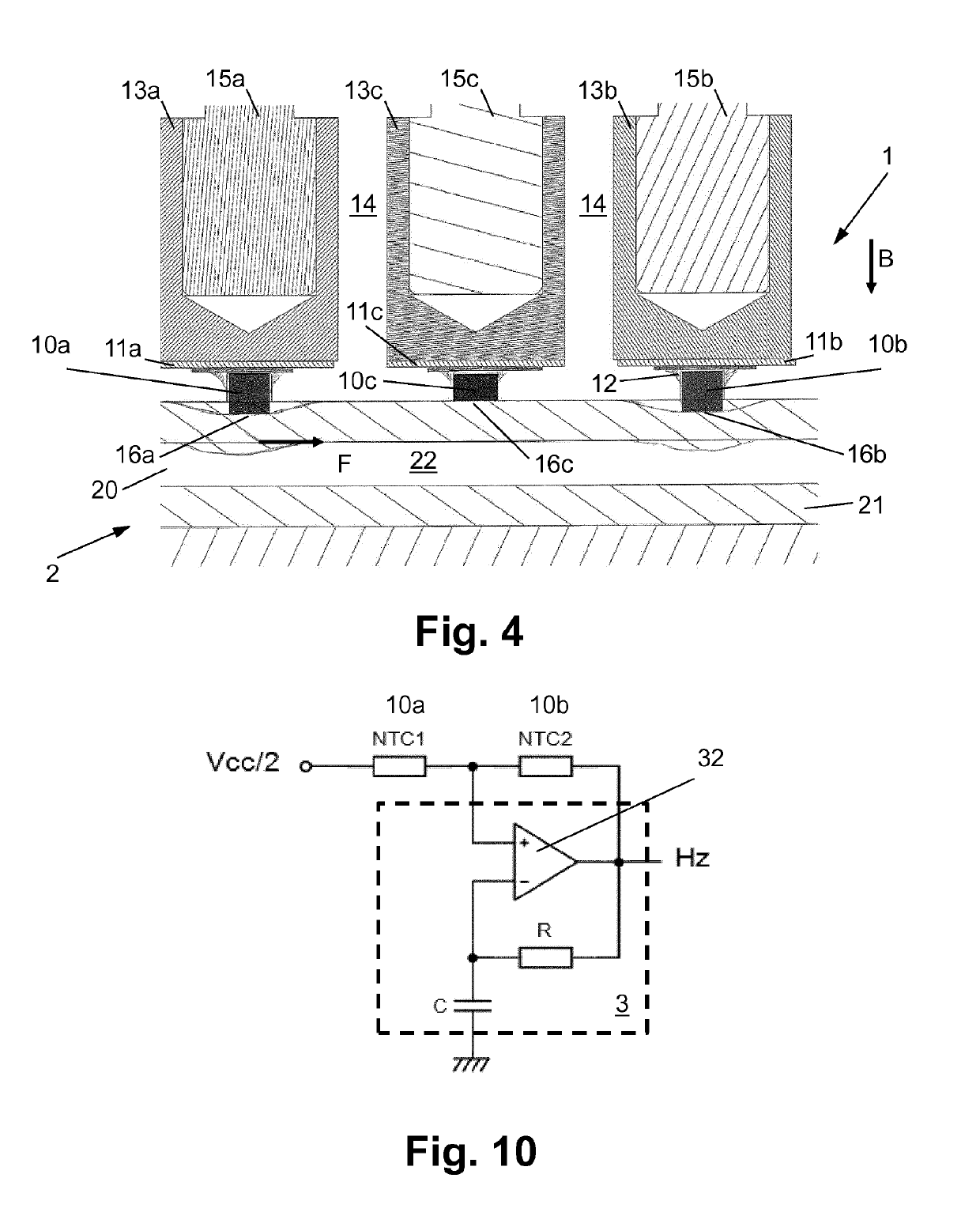
[0112]The thermal flow detector 1 exemplarily includes an upstream thermoelectric element 10a as upstream temperature sensor, a downstream thermoelectric element 10b as downstream temperature sensor, and a middle thermoelectric element 10c that is arranged between the upstream thermoelectric element 10a and the downstream thermoelectric element 10b and serves as heating element. The flow detector 1 further includes a flow detector evaluation unit 3 that generates the flow detector signal from the electric raw signals that are provided by the thermoelectric elements, in particular the upstream thermoelectric element 10a and the downstream thermoelectric element 10b.

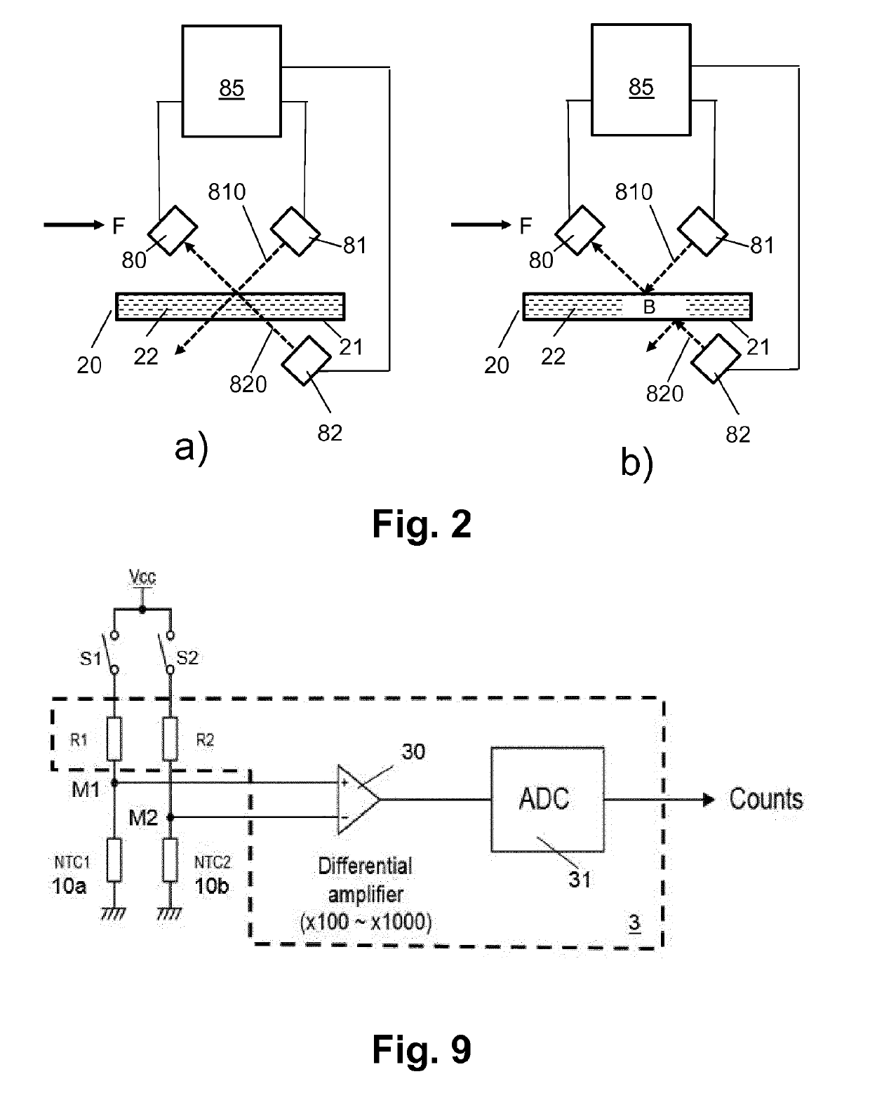
[0113]The optical gas detector 8 exemplarily includes...


PUM


Abstract

Disclosed is a supervision device (9) for supervising liquid drug flow in a flow channel (20). The supervision device (9) includes a flow detector (1), arranged for operatively coupling with the flow channel (20) and generating a flow detector signal in dependence of a flow in the flow channel (20) at a flow detection location. The supervision device (9) further includes a gas detector (8), arranged for operatively coupling with the flow channel (20) and generating a gas detector signal in dependence of whether liquid drug or gas is present in the flow channel (20) at a gas detection location at a distance upstream from the flow detection location. The supervision device (9) further includes a processing unit (90) in operative coupling with the flow detector (1) and the gas detector (8), wherein the processing unit (90) is configured to determine, based on a the gas detector signal, whether non-flowing liquid drug is present at the flow detection location or a gas bubble passes the flow detector if the flow detector signal does not indicate a liquid drug flow.

Description

TECHNICAL FIELD[0001]The present disclosure lies in the field of ambulatory infusion systems and ambulatory infusion devices, as used in a number of therapies, in particular diabetes therapy. More particularly, the disclosure lies in the field of supervising the liquid drug administration.BACKGROUND AND PRIOR ART[0002]Continuous subcutaneous insulin infusion (CSII) is an established state-of the art therapy of diabetes mellitus. It is carried out via sophisticated computer-controlled ambulatory infusion devices that are commercially available from a number of suppliers. Traditionally, such ambulatory infusion devices are realized as miniaturized syringe driver devices and are worn, e.g., in a trousers' pocket, with a belt clip, or the like. Recently, alternative devices have been developed that are directly attached to the patient's skin. Also alternative fluidic designs have been proposed, e.g. downstream dosing architectures with a variable intermediate dosing cylinder, as disclos...

Claims


Application Information

Patent Timeline
Patent Type & Authority Applications(United States)
IPC IPC(8): A61M5/168A61M5/36
CPCA61M5/1684A61M5/365A61M2205/50A61M2205/3334A61M2205/18A61M2205/3306A61M2205/3317A61M2205/3379A61M2005/16872A61M2005/16868A61M5/142A61M5/16831A61M5/172A61M2205/3673
Inventor LIST, HANSWEHOWSKI, FREDERIC
Owner ROCHE DIABETES CARE INC
Why Eureka
Try Eureka