Gap-filling sealing layer of thermal barrier coating

a technology of thermal barrier coating and gap filling, which is applied in the direction of superimposed coating process, coating, chemistry apparatus and processes, etc., can solve the problem of sealing layer breaking off, and achieve the effect of robust surface conta

Inactive Publication Date: 2019-06-27
GM GLOBAL TECH OPERATIONS LLC
View PDF6 Cites 4 Cited by
  • Summary
  • Abstract
  • Description
  • Claims
  • Application Information

AI Technical Summary

Benefits of technology

[0005]The present disclosure provides a sealing layer that fills in gaps or crevices along an outer edge of the insulating layer. For example, the sealing layer may be made of a fine powder that fills in the gaps and / or crevices along the edge of the insulating layer, providing a more robust surface contact between the insulating layer and sealing layer, so that the sealing layer effectively bonds to a substantial majority of the outer surface of the insulating layer.
[0008]The thermal barrier coating has a low thermal conductivity to reduce heat transfer losses and a low heat capacity so that the surface temperature of the thermal barrier coating tracks the gas temperature in the combustion chamber. Thus, the thermal barrier coating allows surface temperatures of the component to swing with the gas temperatures. This reduces heat transfer losses without affecting the engine's breathing capability and without increasing knocking tendency. Further, heating of cool air entering the cylinder of the engine is reduced. Additionally, exhaust temperature is increased, resulting in faster catalyst light off time and improved catalyst activity.

Problems solved by technology

However, given the porosity of the insulating layer, the very thin sealing layer only bonds to some of the surface of the insulating layer.
Further, given the thinness of the sealing layer, the sealing layer may break off when subject to extreme conditions within the combustion chamber.

Method used


Image

  • Gap-filling sealing layer of thermal barrier coating
  • Gap-filling sealing layer of thermal barrier coating
  • Gap-filling sealing layer of thermal barrier coating

Examples


Embodiment Construction

[0022]Those having ordinary skill in the art will recognize that terms such as “above,”“below,”“upward,”“downward,”“top,”“bottom,” etc., are used descriptively for the figures, and do not represent limitations on the scope of the disclosure, as defined by the appended claims.

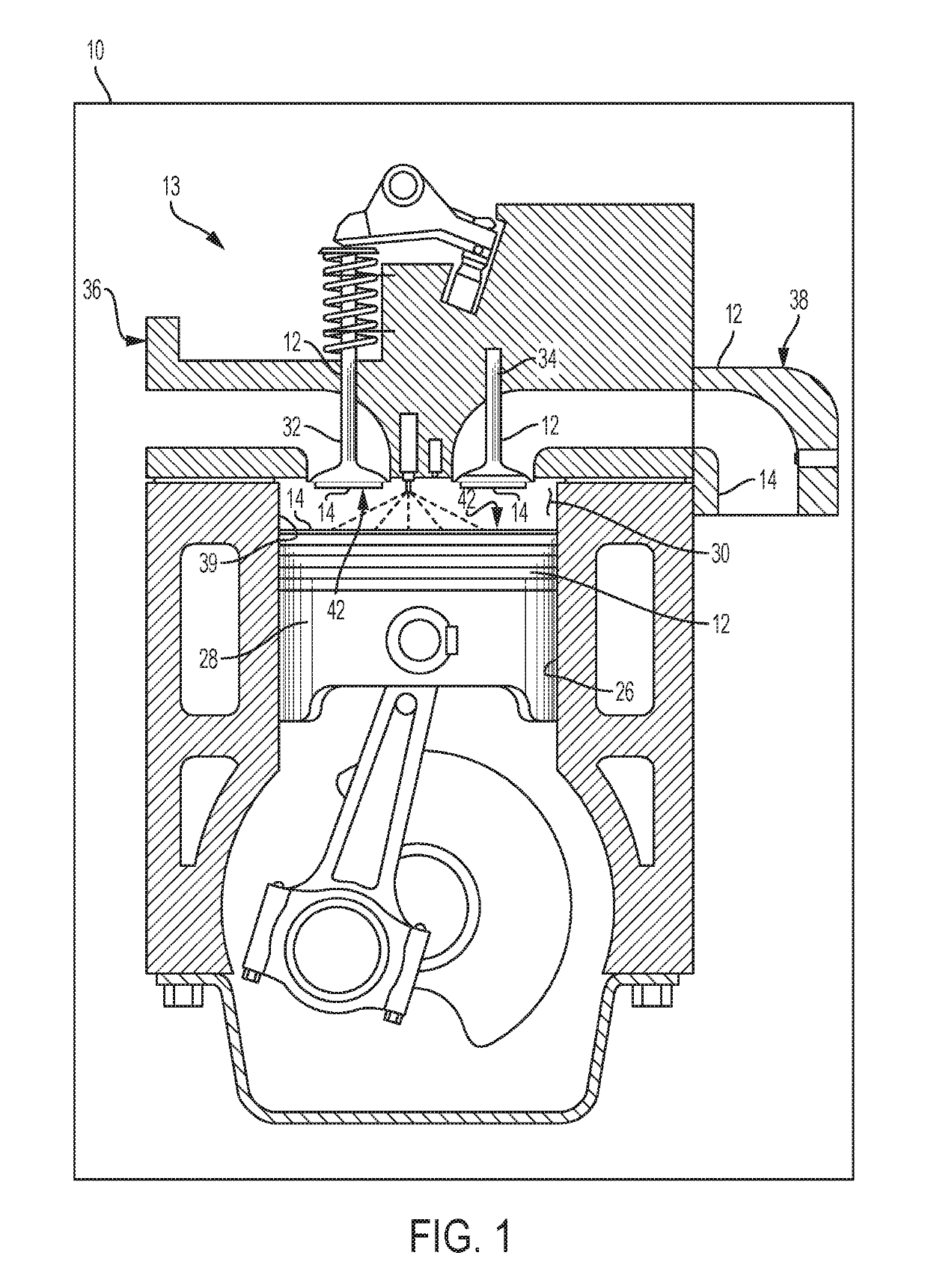
[0023]Referring to the drawings, wherein like reference numbers refer to like components throughout the views, FIG. 1 shows a portion of an example vehicle propulsion system 10 that includes an engine 13 having a component 12. The component 12 has a thermal barrier “coating” (TBC) 14 of the type disclosed herein, applied thereto. The thermal barrier coating 14 may be referred to as a composite thermal barrier coating or multi-layer thermal barrier in forms that have multiple layers bonded together. For example, the TBC 14 may be an engineered surface comprised of a plurality of layers, which is described in further detail below.

[0024]While the engine 13 of FIG. 1 is a typical example application suitable for the...


PUM

PropertyMeasurementUnit
widthaaaaaaaaaa
thicknessaaaaaaaaaa
thicknessaaaaaaaaaa

Abstract

A multi-layer thermal barrier coating is provided that includes an insulating layer having an outer surface defining a plurality of crevices therein and a sealing layer bonded to the outer surface of the insulating layer. The sealing layer is substantially non-permeable and is configured to seal against the insulating layer. The sealing layer fills in at least a portion of the crevices. A method of forming a thermal barrier coating is also provided, which includes a step of providing a plurality of hollow round microstructures bonded together, each having a diameter in the range of 10 to 100 microns to create an insulating layer. The method further includes depositing a plurality of metal particles onto the insulating layer and heating the plurality of metal particles to form a substantially non-permeable sealing layer over the insulating layer.

Description

STATEMENT REGARDING FEDERALLY FUNDED RESEARCH OR DEVELOPMENT[0001]This invention was made with government support under contract no. DE-EE0007754 awarded by the United States Department of Energy. The government has certain rights in the invention.TECHNICAL FIELD[0002]The disclosure relates generally to a thermal barrier layer, which may be referred to as a thermal barrier coating (TBC), for protecting components subject to high-temperature gasses, and a method of forming the same.INTRODUCTION[0003]Internal combustion engines include a plurality of cylinders, a plurality of pistons, at least one intake port, and at least one exhaust port. The cylinders each include surfaces that define a combustion chamber. One or more surfaces of the internal combustion engine may be coated with thermal barrier coatings, or multi-layer thermal barriers, to improve the heat transfer characteristics of the internal combustion engine and minimize heat loss within the combustion chamber. For example, s...

Claims


Application Information

Patent Timeline
Patent Type & Authority Applications(United States)
IPC IPC(8): C23C28/02C23C30/00C22C19/00C22C9/04B32B3/10B32B3/26B32B5/30B32B15/01
CPCC23C28/028C23C28/023C23C28/021C23C30/005C22C19/002C22C9/04B32B3/10B32B3/26B32B5/30B32B15/01B32B2305/026B32B2307/304B32B2311/12B32B2311/20B32B2311/22B32B2311/30C01P2004/34C01P2004/61C01P2006/32C23C28/022
Inventor WALKER, MICHAEL J.NAJT, PAUL M.DURRETT, RUSSELL P.ANDRUSKIEWICZ, IV, PETER P.
Owner GM GLOBAL TECH OPERATIONS LLC
Why Eureka
Try Eureka