Additive manufacture system using light valve device

Pending Publication Date: 2019-07-04
EOS OF NORTH AMERICA INC +1
View PDF4 Cites 1 Cited by
  • Summary
  • Abstract
  • Description
  • Claims
  • Application Information

AI Technical Summary

Benefits of technology

[0003]In accordance with one aspect of the invention, an object build area is exposed to a radiation beam, such as a laser light source, which has been processed and controlled through a grating light valve or valves (GLV). It is therefore possible to melt, sinter, fuse or cure predetermined portions of the build area corresponding to the equivalent of individually controlled pixels,

Problems solved by technology

The speed of scanning of a laser beam is of course limited by a single focus point (when one laser is used),

Method used


Image

  • Additive manufacture system using light valve device
  • Additive manufacture system using light valve device
  • Additive manufacture system using light valve device

Examples


Embodiment Construction

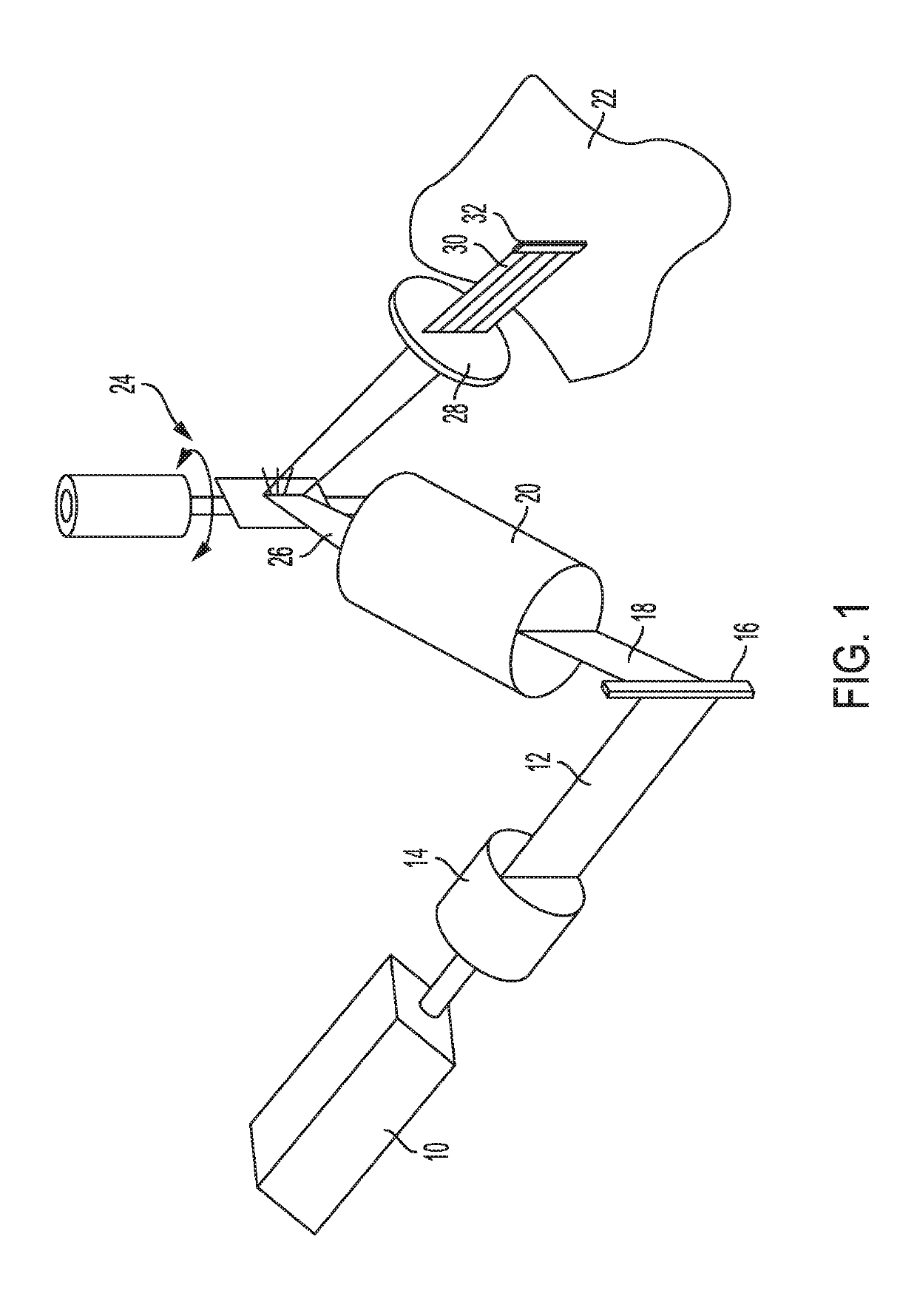
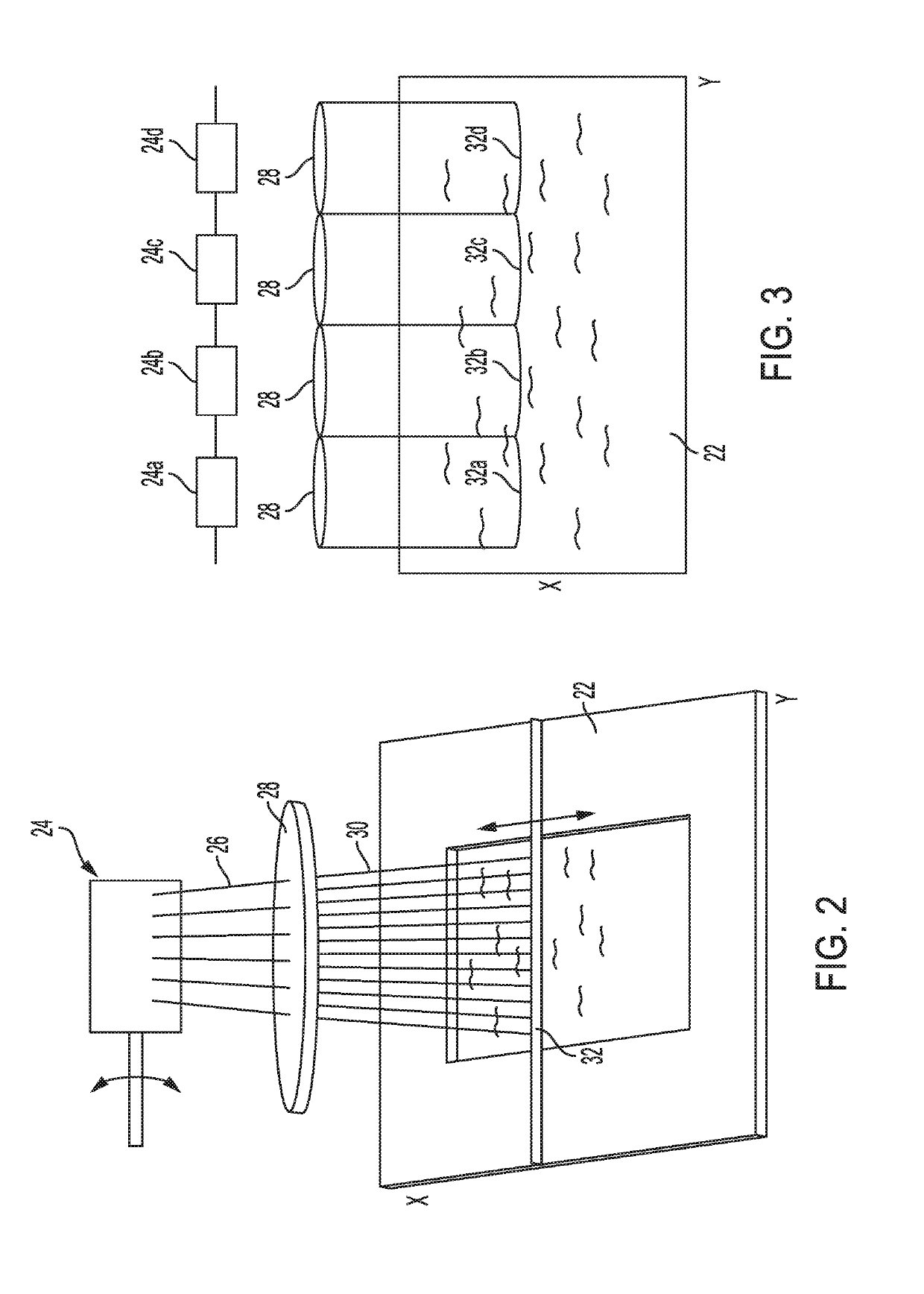
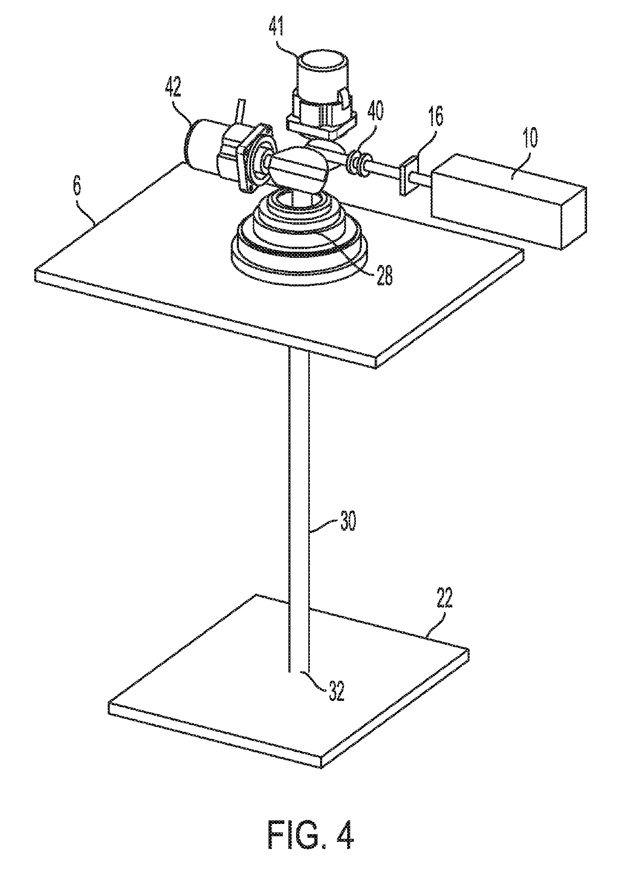
[0019]Referring now to FIG. 1, an embodiment is shown in schematic presentation using an exemplary arrangement of major components. A radiation source, such as light source 10 in the form of a standard 808 nanometer laser at 120 W, is focused to a planar beam 12 using appropriate optics, such as a slit aperture or lens. The planar beam 12 is then focused upon a grating light valve 16 (GLV), which is a form of spatial light modulator of the MEMS (micro electro mechanical systems) type. The output 18 from the GLV is then processed through a beam expander lens 20 to an operational width for application to the object build area 22. More will be described about the GLV and its operation momentarily. Completing the major components of this particular embodiment is a scanner 24 (single galvo) which moves the expanded beam 26 through an F-theta lens 28, which is used for distortion correction. The ultimate beam 30 from the lens 28 is then a fairly elongated linear array 32 or line segment, ...


PUM

PropertyMeasurementUnit
Temperatureaaaaaaaaaa
Areaaaaaaaaaaa
Surfaceaaaaaaaaaa

Abstract

An object build area is exposed to a radiation beam, such as a laser light source, which has been processed and controlled through a grating light valve or valves, or planar light valve, to thereby melt, sinter, fuse or cure predetermined portions of the build area corresponding to the equivalent of individually controlled pixels, with rapid movement and positioning of the resulting LV application output array on the build area. The LV arrangement is adapted to also generally heat an entire powder bed, or targeted areas of the bed, to just below melting temperature.

Description

FIELD OF THE DISCLOSURE[0001]The present invention relates to additive manufacture wherein successive layers of an object or workpiece are built up from a powder, fluid or other fluent medium according to previously determined successive so-called 2 dimensional “slices” of the object or workpiece, and more particularly to a system and method using an improved grating light valve and an energy beam (e.g., laser) which can be rapidly scanned across the build area for significantly increased build speed.BACKGROUND OF THE INVENTION[0002]Additive prototyping or manufacture techniques using a laser or other energy beam to melt, fuse, cure, sinter or otherwise solidify material to build an object or workpiece (hereafter simply referred to as an object) in a layerwise manner are well known. It is a continuing effort in the field to speed up the build process, to thereby shorten the time required to build an object. In one standard approach, an energy beam, such as a laser beam, is focused t...

Claims


Application Information

Patent Timeline
IPC IPC(8): B29C64/268B29C64/153B33Y10/00B33Y30/00B23K26/082B23K26/064B23K26/062B23K26/073B23K26/342B23K26/70
CPCB29C64/268B29C64/153B33Y10/00B33Y30/00B23K26/082B23K26/064B23K26/062B23K26/073B23K26/342B23K26/704B29C64/129B29C64/286G02B26/101B22F12/44B22F10/362B22F10/366Y02P10/25
Inventor VANELLI, DONALD LEWISSHANKLIN, LANCE BRUCEHAYES, GREGORY RICHARDPFEIFFER, HAKAN
Owner EOS OF NORTH AMERICA INC
Why Eureka
Try Eureka