Multi-functional cementitious materials with ultra-high damage tolerance and self-sensing ability

a cementitious material and multi-functional technology, applied in the direction of ceramicware, solid waste management, sustainable waste treatment, etc., can solve the problems of high risk of fracture failure, cracking, deterioration and damage, and high difficulty in detecting cracking, deterioration or damage in concrete,

Pending Publication Date: 2019-07-04
RGT UNIV OF CALIFORNIA
View PDF4 Cites 16 Cited by
  • Summary
  • Abstract
  • Description
  • Claims
  • Application Information

AI Technical Summary

Benefits of technology

[0040]FIGS. 5A-5D show the effect of carbon black nanoparticles on tensile-strain relation of an initial design (not the final MSC design). FIG. 5A shows effect of 0% carbon black nanoparticles on tensile-strain relation of an initial design (not the final MSC design). FIG. 5B shows the effect of 2.5% carbon black nanoparticles on tensile-strain relation of an initial design (not the final MSC design). FIG. 5C shows the effect of 5% carbon black nanoparticles on tensile-strain relation of an initial design (not the final MSC design). FIG. 5D shows the effect of 10% carbon black nanoparticles on tensile-strain relation of an initial design (not the final MSC design).
[0041]FIG. 6 shows the effect of carbon black nanoparticle content on cementitious matrix fracture toughness.
[0042]FIGS. 7A-7D show fiber bridging cohesive stress vs. crack opening (σ˜δ) relation. FIG. 7A shows the effect of 0%, 2.5%, 5%, and 10% carbon black nanoparticle content on the σ˜δ relation. FIG. 7B shows the σ˜δ relations of SHC-2.5% CB (initial design) and MSC-2.5% CB (redesign). FIG. 7C shows the σ˜δ relations of SHC-5% CB (initial design) and MSC-5% CB (redesign). FIG. 7D shows the σ˜δ relations of SHC-10% CB (initial design) and MSC-10% CB (redesign).

Problems solved by technology

The long-term durability and safety of concrete infrastructure are vital to national prosperity, but are challenged by two fundamental limitations: 1) concrete is quasi-brittle in nature and susceptible to cracking, deterioration and damage under various mechanical and environmental loads; and 2) it is highly difficult to detect cracking, deterioration or damage in concrete or reinforced concrete structural components, especially with spatial resolution, using current structural health monitoring approaches in practice.
Concrete is an inherently quasi-brittle material with low fracture energy (e.g., order of 0.1 kJ / m2); thus, it is highly susceptible to cracking and fracture failure under mechanical and environmental loads.
Under service conditions, cracking causes local stress concentration, and compromises concrete transport properties to facilitate chemical attack, moisture and chloride penetration, and reinforcement corrosion.
Under extreme events such as earthquakes or impact, the low fracture energy of concrete can result in concrete cracking, spalling and fragmentation, loss of bond with reinforcing steel, and catastrophic structural failure.
Current management practices mainly rely on regular visual inspections, which can be subjective and limited to accessible locations.
The indirect, point-based sensing approach is costly, requires complex analytical models to correlate the local measurements to structural mechanical state, and is highly difficult to provide spatial information on strain and damage.
Despite these advances, the fundamental linkage between the microstructure and the electromechanical behavior of cementitious materials is not yet well understood.
Due to its highly heterogeneous microstructure, a cementitious material cannot be represented by an ideal resistor, and its electrical response is frequency-dependent.
These methods often require costly instrumentation, intricate network of sensors, and suffer from signal attenuation due to the heterogeneous nature of concrete and data contamination due to background noise and secondary sources.
They are significantly more difficult to apply to concrete structures than metallic structures.

Method used


Image

  • Multi-functional cementitious materials with ultra-high damage tolerance and self-sensing ability
  • Multi-functional cementitious materials with ultra-high damage tolerance and self-sensing ability
  • Multi-functional cementitious materials with ultra-high damage tolerance and self-sensing ability

Examples


example 1

[0098 Design of Strain-Hardening Cementitious Composites.

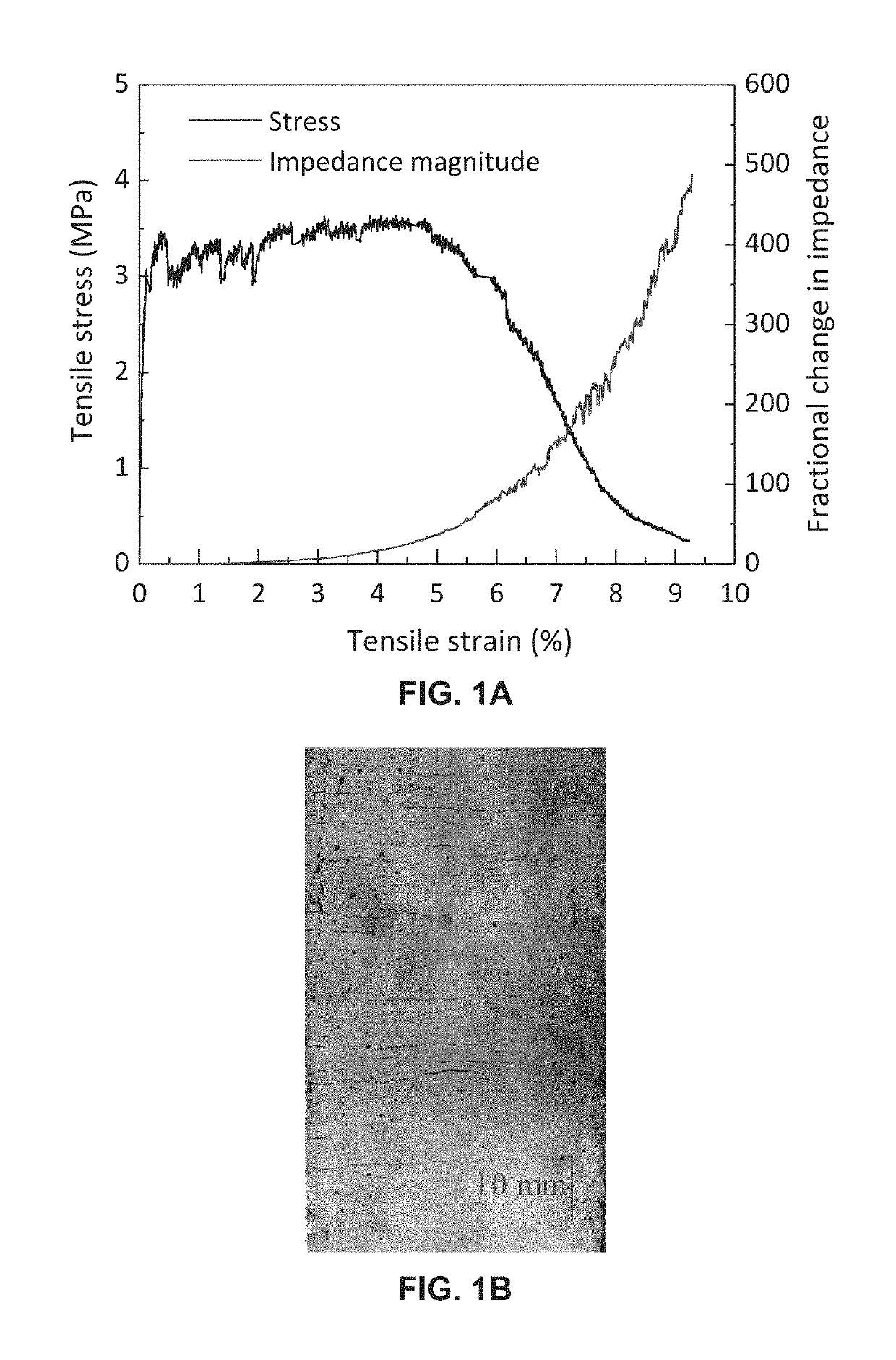
[0099]The high-performance damage tolerance of MSC is achieved by transforming the brittle behavior of cementitious materials to a ductile behavior similar as metals under tension. Under tension, the MSC material exhibits pseudo-strain-hardening behavior (FIG. 1A) accompanied by the sequential formation of multiple microcracks (FIG. 1B). This is in contrast with the brittle behavior of concrete with localized cracking formation. Each of the small stress “drops” on the stress-strain curve corresponds to the formation of a micro-crack that leads to a release of energy. The material design was achieved by integrating ingredient proportioning, rheology control during processing, and nano- and micro-structure tailoring. The cementitious matrix cracking behavior and the fiber / matrix interface were engineered through the nanoparticles and pozzolanic ingredients to dissipate energy through steady-state crack propagation and multiple m...

example 2

[0101 Effect of CB Nanoparticles on Material Electrical Microstructure and Parameters.

[0102]FIGS. 4A-4D data suggest that the strongest piezoresistive behavior can be achieved at around 5% CB content for a particular cementitious mix design. Beyond 5%, the decrease in R2 slows down and the increase in C2 becomes much faster (note the log scale), indicating that further increasing CB content reduces partially conductive paths by converting them into conductive paths. This study revealed the critical role of partially conductive paths, showing that strong electromechanical behavior can be achieved at an optimal range rather than the highest amount of CB nanoparticles.

example 3

[0103 Effect of CB Nanoparticles on Material Tensile Behavior.

[0104]Direct uniaxial tension tests were conducted on coupon specimens with the initial mix designs shown in Table 1. The tests were performed at a fixed displacement rate of 0.0025 mm / sec. The specimens were gripped at both ends by the testing system with a gripping length of 51 mm. Two LVDTs were attached to the sides of each specimen with a gauge length of 152 mm. FIG. 5 shows the measured tensile stress-strain curves. It was observed that the increasing amount of CB nanoparticles led to a decrease in material first-cracking stress, tensile strain capacity, and tensile strength. The first-cracking stress is defined as the tensile stress at which the first microcrack appears. The tensile strain capacity is defined as the strain corresponding to the tensile strength. Based on the average of three repeat specimens for each mix design, the tensile strain capacity decreased from above 5% to below 2% when CB nanoparticles we...


PUM

PropertyMeasurementUnit
particle sizeaaaaaaaaaa
diameteraaaaaaaaaa
diameteraaaaaaaaaa

Abstract

Cementitious materials having high damage tolerance and self-sensing ability are described herein. These materials may replace conventional concrete to serve as a major material component for infrastructure systems with greatly improved resistance to cracking, reinforcement corrosion, and other common deterioration mechanisms under service conditions, and prevents fracture failure under extreme events. These materials can also be used for the repair, retrofitting or rehabilitation of existing concrete structures or infrastructure systems. Furthermore, these materials may offer capacity for distributed and direct sensing of cracking, straining and deterioration with spatially continuous resolution wherever the material is located, without relying on installation of sensors. The present invention relates to multifunctional cementitious structural or infrastructure materials that integrate self-sensing with damage tolerance for improving safety, extending service life, and health monitoring of structures, components, and infrastructure systems.

Description

CROSS-REFERENCES TO RELATED APPLICATIONS[0001]This application is a continuation-in-part, and claims benefit of U.S. patent application Ser. No. 16 / 229,519, filed Dec. 21, 2018, which claims benefit of U.S. Provisional Patent Application No. 62 / 609,929, filed Dec. 22, 2017, the specification(s) of which is / are incorporated herein in their entirety by reference.STATEMENT REGARDING FEDERALLY SPONSORED RESEARCH OR DEVELOPMENT[0002]This invention was made with government support under Grant No. DE-AC07-051D14517, #168284 awarded by the Department of Energy. The government has certain rights in the invention.BACKGROUND OF THE INVENTIONField of the Invention[0003]The present invention relates to multifunctional strain-hardening cementitious (MSC) structural materials or infrastructure materials that integrate ultra-high damage tolerance with self-sensing functionality for improving infrastructure or structural safety and durability, extending service life, and monitoring structural health...

Claims


Application Information

Patent Timeline
Patent Type & Authority Applications(United States)
IPC IPC(8): C04B28/04C04B14/06C04B18/08C04B14/02C04B16/06C04B18/14C04B24/26
CPCC04B28/04C04B14/06C04B18/08C04B14/022C04B16/0641C04B18/146C04B24/2641C04B2103/32C04B2111/94C04B2111/2038C04B2111/34Y02W30/91C04B20/0048C04B20/008C04B38/0054C04B2103/0079C04B2103/0088C04B2103/10C04B2103/20C04B14/386C04B14/4668C04B16/0625C04B16/0633C04B24/2647C04B14/026C04B14/30C04B14/34
Inventor LI, MOLI, XIAOPENG
Owner RGT UNIV OF CALIFORNIA
Why Eureka
Try Eureka