Submerged Vehicle Localization System and Method

a submerged vehicle and localization technology, applied in the direction of instruments, beacon systems using ultrasonic/sonic/infrasonic waves, measurement devices, etc., can solve the problems of increasing the acoustic noise of the system, reducing the fidelity of the system, and prone to errors in signal measurement and calculation by the receiving vehicle. achieve low-cost yet accurate localization

Pending Publication Date: 2019-07-04
WOODS HOLE OCEANOGRAPHIC INSTITUTION
View PDF0 Cites 31 Cited by
  • Summary
  • Abstract
  • Description
  • Claims
  • Application Information

AI Technical Summary

Benefits of technology

[0013]An object of the present invention is to enable low-cost yet accurate localization by one or more secondary vehicles within a liquid body relative to a single source of time-synchronized acoustic signals.

Problems solved by technology

However, GPS signals does not penetrate into liquid bodies (e.g. the ocean), and submerged vehicles must rely on other methods to determine their precise location.
Underwater positing systems have been developed, but these have major drawbacks, relying either on multiple stationary acoustic beacons, or large and power-hungry devices systems.
Also, the reliance on multiple transmitters increases the acoustic noise of the system, making signal measurement and calculation by the receiving vehicle error-prone, decreasing the fidelity of the system.
Furthermore, LBL systems typically require two-way time-travel (TWTT).
The local terrain in any of these environments can be very complex, and any vehicle operating in such an environment must know its location in order to effectively carry out its desired operation.
Current underwater localization methods are costly, large and power hungry (i.e. requiring significant power supplies); thus increasing the size and expense of an underwater vehicle incorporating such a system.
Due to size, weight and cost constraints for small AUVs, and the physical complexity and characteristics of the underwater environment, a single AUV can only record a limited amount of data with its on-board instrumentation, requiring more time and movements to cover the desired area.
However, there are significant practice challenges to the use of AUV formations in submerged environments.
Larger submergible vehicles such as submarines and large AUVs have specialized, high quality navigation systems, but larger vehicles are costly, not well adapted for use in formations, and require substantial support capabilities between missions.
Small, inexpensive AUVs, while well adapted for use in formations, cannot utilize the large, heavy, costly and power-hungry navigation systems of larger AUVs.
Therefore, small AUVs experience significant navigation errors, which accumulate rapidly, on the order of tens of meters per minute.
These navigation errors present a significant hurdle for the use of small AUVs in formation or networked activities.
However, their method only achieved low-quality results with unacceptably large errors in estimated range and bearing to a fixed acoustic source, and was only possible in a non-real-time manner.
A mobile-source utilizing this method would have had even greater range and bearing error.

Method used


Image

  • Submerged Vehicle Localization System and Method
  • Submerged Vehicle Localization System and Method
  • Submerged Vehicle Localization System and Method

Examples


example 1

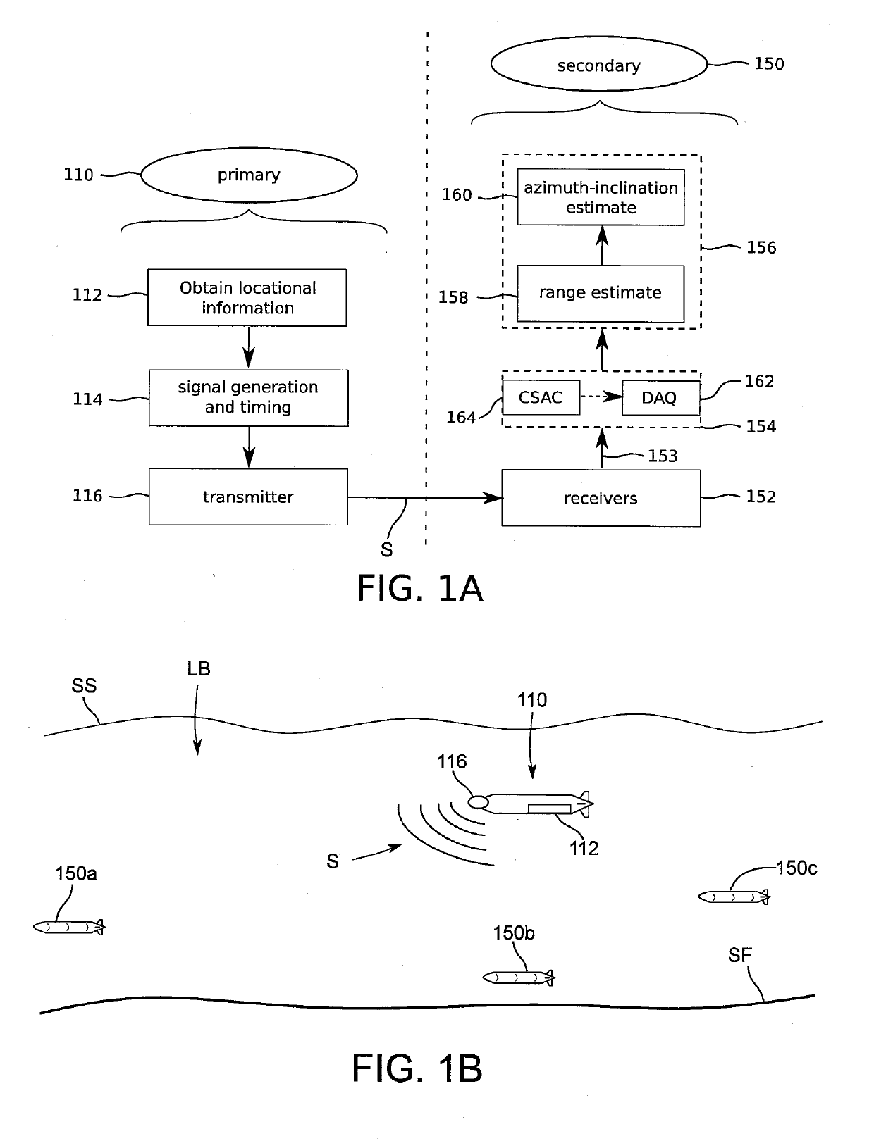
[0156]Referring to FIGS. 7A-7F, experiments were performed using our SandShark AUV with acoustic payload (i.e. the secondary payload 151) on a portion of the Charles River by the MIT Sailing Pavilion. Our acoustic beacon (i.e. the primary 110) was submerged to about 0.5 m depth and fastened to the pavilion dock, at a known GPS position 710c and 710f. The AUV was pre-programmed with a mission where it was instructed to travel back-and-forth along the dock for 170 m at 2 m depth and a speed of 1.4 m / s. The mission duration was set to 1200 s, and the AUV was instructed to surface for a 120 s GPS fix 712a-712g whenever it was at the end of a 170 m run and the time since the last fix was greater than 150 s.

[0157]Both matched filtering and phased-array beamforming were performed on the Raspberry Pi 3 in real-time at approximately 1.25 Hz with 4050 look-angles (15 inclination and 270 azimuth equally-spaced angles). This data was recorded by the payload along with pre-filtered navigation da...

example 2

[0164]To demonstrate single-beacon piUSBL absolute navigation, we carried out two additional closed-loop deployments (designated run 3 and run 4) of our SandShark AUV on a portion of the Charles River adjacent to the MIT sailing pavilion, illustrated in FIGS. 8A-8D. Our custom acoustic beacon (i.e. primary 810) was set to broadcast a 20 ms, 16-18 kHz linear frequency modulated (LFM) up-chirp, and was affixed to the pavilion dock and submerged to a depth of approximately 1 m. The SandShark (i.e. a secondary vehicle 150 plus payload 151) was programmed to run a mission to follow a racetrack parallel to the dock of 90 m length and 10 m width, at a depth of 2 m and a speed of 1 m / s. The mission length was set to 1200 s, with the vehicle instructed to surface for GPS approximately mid-way through the mission.

[0165]Since GPS is unavailable underwater, we also deployed two commercial Hydroid LBL transponders 811a, 811b fastened to the pavilion at a depth of approximately 1 m, with the firs...

example 3

Relative Autonomy for Command and Control

[0181]The objective of this example is a secondary vehicle command and control methodology that is easy to maintain as secondary vehicle formations scale up in number, while providing accurate acoustic navigation for a new generation of miniature, lowcost AUVs that lack high-fidelity navigational sensors (i.e. a DVL-aided INS). This method was demonstrated in field trials in which three SandShark AUVs were placed in the water, and were commanded to different patterns based on the broadcast acoustic waveform and position of a single beacon (i.e. primary) in the Charles River.

[0182]The implications for this operational paradigm are to make multi-vehicle operations easier on the operator. Each AUV has a unique identifier assigned automatically on launch, and which determines parameterized offsets in x (Δx), y (Δy), depth (Δz), range (r) and heading (θ) retrieved from a pre-defined look-up table. Desired vehicle state in each operational mode is ...


PUM


Abstract

An inexpensive acoustic beacon-type system suitable for the self-localization of one or more submergable secondary vehicles such as AUVs. A single beacon in a primary system periodically transmits an acoustic signal to the secondary vehicle. The acoustic signal is passively received by at least two receivers such as an AUV-mounted ultra-short baseline (USBL) array, which enables multiple vehicles to localize using just a single beacon. A controller (i) maintains time-synchronization with the primary system, (ii) develops a range estimate signal from measurements of received signals from at least two receivers and (iii) develops an azimuth-inclination estimation of likeliest angle-of-arrival of the primary signals, wherein the controller utilizes a plurality of coordinate frames to provide an estimate of secondary system location.

Description

CROSS-REFERENCE TO RELATED APPLICATION[0001]This application claims priority to U.S. Provisional Application No. 62 / 612,520 filed Dec. 31, 2017, the contents of which are hereby incorporated as if set forth herein in its entirety.STATEMENT REGARDING GOVERNMENT LICENSE RIGHTS[0002]This invention was made with U.S. Government support under N00014-16-1-2081 awarded by the Office of Naval Research. The U.S. Government has certain rights in this invention.FIELD OF THE INVENTION[0003]This invention relates to determining the location of submerged vehicles. More particularly to one-way transmission of time-synchronized signals and real-time processing to facilitate low-cost self-navigation within a liquid body.BACKGROUND OF THE INVENTION[0004]Precise locational information is critical for practically any autonomous vehicle, robot, or other object. Location-determining solutions for terrestrial vehicles exist, including GPS positioning. However, GPS signals does not penetrate into liquid bo...

Claims


Application Information

Patent Timeline
Patent Type & Authority Applications(United States)
IPC IPC(8): G01S11/14H04B13/02
CPCG01S11/14H04B13/02G01S1/76G01S1/74G01S5/28G01S3/803G01S3/802
Inventor SCHMIDT, HENRICKRYPKEMA, NICHOLAS R.FISCHELL, ERIN
Owner WOODS HOLE OCEANOGRAPHIC INSTITUTION
Why Eureka
Try Eureka