
Solid-state line disturbance circuit interrupter

a circuit interrupter and solid-state technology, applied in the field of power distribution systems, can solve the problems of excessive current that trips either the circuit breaker or the gfi device, further complicated arc fault sensing scheme, and immediate fire hazards, and achieves low cost, high efficiency, and low voltage

Active Publication Date: 2019-07-04
INTELESOL LLC
View PDF0 Cites 33 Cited by
  • Summary
  • Abstract
  • Description
  • Claims
  • Application Information

AI Technical Summary

Benefits of technology

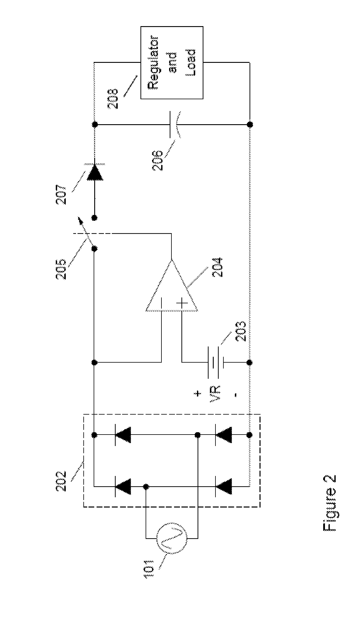
This patent describes a system for efficiently converting alternating current (AC) to direct current (DC) for use in electronic devices. The system includes a switch and a regulator circuit, which work together to reduce power dissipation and improve efficiency. The switch disconnects the regulator circuit during normal operation to save power, while the regulator circuit accumulates energy when the switch is closed. When the AC mains voltage exceeds a certain threshold, the switch is opened and energy is supplied to the load through the regulator circuit. The system also includes a comparator to control the switch, which can be designed using operational amplifiers or MOS field effect transistors. Overall, this system provides a compact, integrated, and highly efficient solution for connecting low-voltage electronic devices to AC power.

Problems solved by technology

An arc fault occurs when two conductors in a circuit become so closely spaced that electrical breakdown of the intervening material occurs allowing current to flow intermittently between the conductors.
The breakdown and resulting current flow are accompanied by extremely high temperatures, well above the ignition point of typical construction materials thereby presenting an immediate fire hazard in the vicinity of the arc fault.
Arc faults that occur from line to line, line to neutral or line to ground are termed parallel arc faults and typically result in excessive current that trips either the circuit breaker or the GFI device.
The arc fault sensing scheme is further complicated by a need to minimize false triggers caused by complex loads like switching power supplies and dimmer circuits which exhibit current-voltage relationships that mimic arc faults.
The sophisticated arc fault sensing schemes typically require more complex circuitry than the simple and bulky electromechanical devices employed in prior art circuit breakers and GFIs.

Method used


Image

  • Solid-state line disturbance circuit interrupter
  • Solid-state line disturbance circuit interrupter
  • Solid-state line disturbance circuit interrupter

Examples


Embodiment Construction

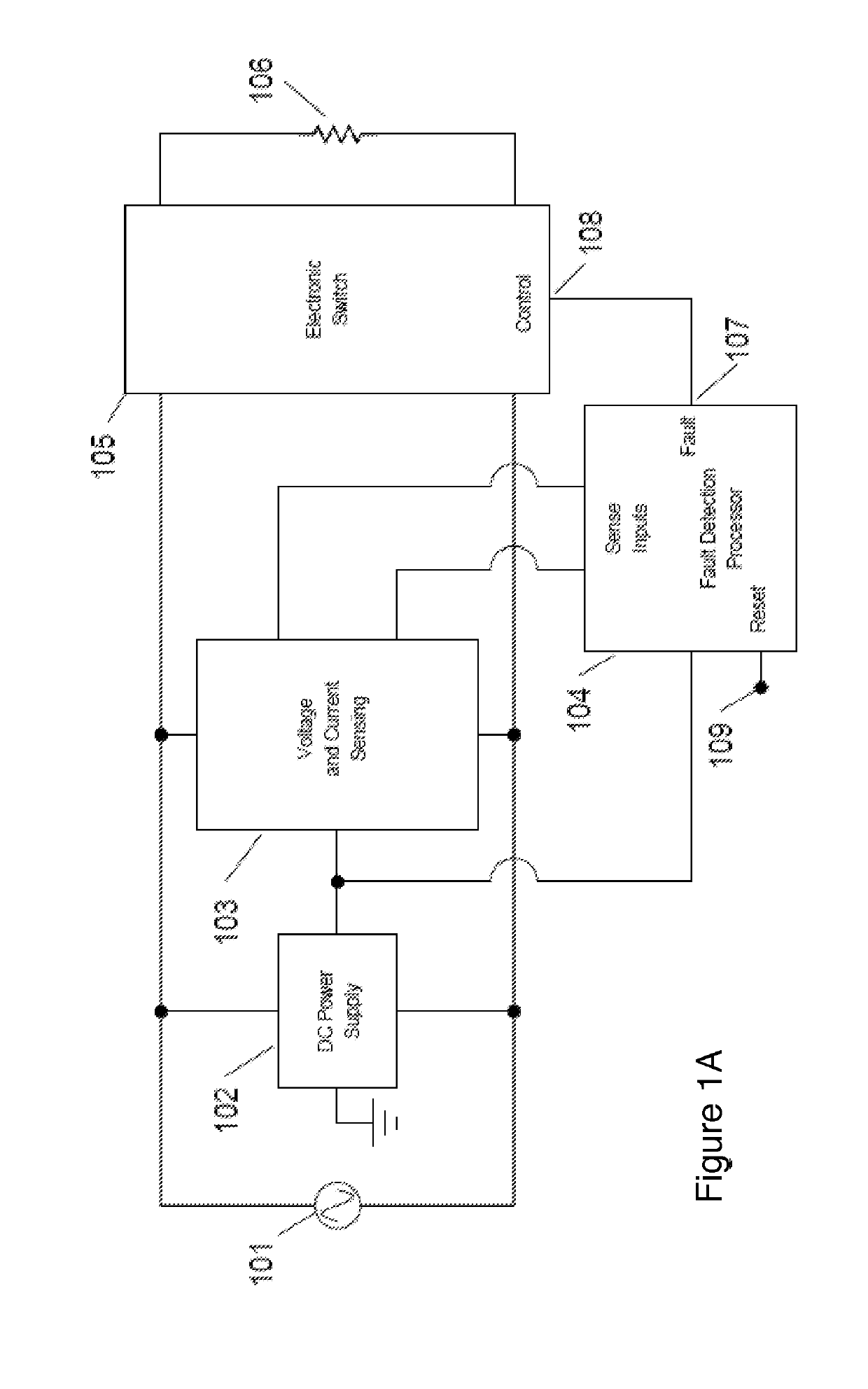
[0019]Commonly numbered items in all the Figures refer to the same item throughout the description. FIG. 1A is a block diagram showing the key elements of the solid-state circuit interrupter. AC mains 101 is connected to load 106 through electronic switch unit 105. A low voltage DC power supply 102 efficiently provides power for mains voltage and current sensing circuit 103 and the fault detection processor 104. Sense inputs to the fault detection processor 104 are provided from the voltage and current sensing circuit 103. The solid-state sensing circuit comprising sensors that sense the waveforms of the voltage and current applied to the load circuit, and, develop proportional analog waveforms. The fault detection processor processes the proportional analog waveforms and upon detection of either a ground fault or an arc fault generates a fault output 107.

[0020]Upon detection of a fault, the Fault output 107 of the fault detection processor 104 is latched and fed to the control inpu...


PUM


Abstract

The invention relates to a novel approach for the protection of electrical circuits from ground faults and parallel and series arc faults in a fully solid-state circuit configuration. Solid-state circuits and methods of use are described that provide the key functions of low-voltage DC power supply, mains voltage and current sensing, fault detection processing and high voltage electronic switching.

Description

CROSS-REFERENCE TO RELATED APPLICATIONS[0001]This application claims priority to: U.S. Provisional Patent Application 62 / 414,467, Titled: High Efficiency AC to DC Converter and Methods, Filed Oct. 28, 2016. U.S. Provisional Patent Application 62 / 333,193, Titled: AC Direct power management semiconductor device and power management method, Filed May 7, 2016, U.S. Provisional Patent Application 62 / 335,495, Titled: AC Direct LVO Electronic Dimming Switch, Filed May 12, 2016, and, U.S. Provisional Patent Application 62 / 431,926, Titled: Electronic Switch and Dimmer, Filed Dec. 9, 2016, all of which include a common inventor, are currently pending and are hereby incorporated by reference in this application.STATEMENT REGARDING FEDERALLY SPONSORED RESEARCH OR DEVELOPMENT[0002]Not Applicable.BACKGROUND OF THE INVENTIONTechnical Field[0003]The invention relates to a power distribution system and in particular to a fully solid-state circuit interrupter for disconnecting power from a distributi...

Claims


Application Information

Patent Timeline
IPC IPC(8): H02H3/00H02H1/00H02H9/08H02M7/217G01R15/20G01R19/00
CPCH02H3/00H02H1/0007H02H1/0092H02H9/08H02M7/217G01R15/202G01R19/0092H02M7/06H02H1/0015H02H1/06H02H3/33H02H3/50H02H3/52H02M1/32G01R31/52G01R31/3277
Inventor TELEFUS, MARKLARSON, BRADLEYRODRIGUEZ, HARRYGERBER, STEPHEN C.
Owner INTELESOL LLC
Learn More