Crankcase ventilation management devices, systems, and methods

a technology of ventilation management and crankcase, applied in crankcase ventillation, machines/engines, centrifuges, etc., can solve the problems of gas leakage past the piston ring, intake valve guide, seals at a heightened rate, supercharged or turbocharged engines, etc., and achieve the effect of adsorption flexibility

Active Publication Date: 2019-07-11
KUHN PERFORMANCE TECH LLC
View PDF0 Cites 9 Cited by
  • Summary
  • Abstract
  • Description
  • Claims
  • Application Information

AI Technical Summary

Benefits of technology

[0016]In some implementations, the centrifugal separator can be powered by an electric motor. The electric motor can provide additional flexibility for placement of the centrifuge within the engine bay of the vehicle. The motor and / or the pump or other electric components of the centrifuge can be powered through the alternator and / or the battery of the vehicle. Some variants are powered by a power take off shaft from the engine.

Problems solved by technology

Many piston-driven internal combustion engines that see rigorous use, and / or create large amounts of power generate blow-by gases.
Supercharged or turbocharged engines, in particular, can have problems with blow-by gases because such engines typically run with higher internal pressures and create pressures in the intake and / or exhaust manifolds.
Supercharged and / or turbocharged engines are prone to having gases leak past the piston rings, intake valve guides, intake valve seals, and / or the exhaust valve guides and seals at a heightened rate as compared to their normally aspirated counterparts.
However, the amount of blow-by, and / or the amount of oil carried by the blow-by gases, may be too excessive to introduce back into the intake system without negative consequences.
Excessive oil can, for example, lower fuel octane that promotes detonation which can severely damage engine parts.
This can be a messy, inefficient, and / or illegal method to deal with blow-by gases.
This can result in loss in performance, decreased efficiency, and / or increased maintenance.
This can incur substantial expense to remove, clean, and reseal the intake, as well as inconveniently place the vehicle out of service.
Previous attempts to address the issue of blow-by gases inadequately processed (e.g., cleaned) by the blow-by gases, required excessive maintenance or replacement of parts, encourage circumvention of legal environmental requirements, and / or provided limited engine configuration options (for either after-market or manufacturer solutions).
In the aircraft industry, it was common to direct blow-by gases outside the fuselage, which would often leave oil residue on the side of the aircraft.
This approach is generally too inefficient for a modern high performance engine and / or leaves too much oil in the gases directed to the intake.
For example, the screens can become clogged, requiring regular cleaning and / or replacement of the filter tube.
Another flawed solution included a device having a built-in pop-off valve, replaceable filter media, and easy access cap.
This approach is generally too inefficient for a modern high performance engine and requires frequent maintenance and replacement of the filter media.
The filter media, however, can become an air restriction point as it fills and becomes clogged with oil and particulate deposits.
An additional drawback is the physical size of such devices.
In some situations, the catch can is left open to the atmosphere, which can violate emissions laws and can emit a foul odor.
The filter media and / or screens can become clogged, thereby requiring regular cleaning and / or replacement of the catch-can or components thereof.
However, due to the reduced size of engine bays in modern cars, it can be difficult to install an aftermarket air / oil separator in the engine bay.

Method used


Image

  • Crankcase ventilation management devices, systems, and methods
  • Crankcase ventilation management devices, systems, and methods
  • Crankcase ventilation management devices, systems, and methods

Examples


Embodiment Construction

[0035]The various features and advantages of the systems, devices, and methods of the technology described herein will become more fully apparent from the following description of the embodiments illustrated in the figures. These embodiments are intended to illustrate the principles of this disclosure, and this disclosure should not be limited to merely the illustrated examples. The features of the illustrated embodiments can be modified, combined, removed, and / or substituted as will be apparent to those of ordinary skill in the art upon consideration of the principles disclosed herein.

A. Blow-By Gases

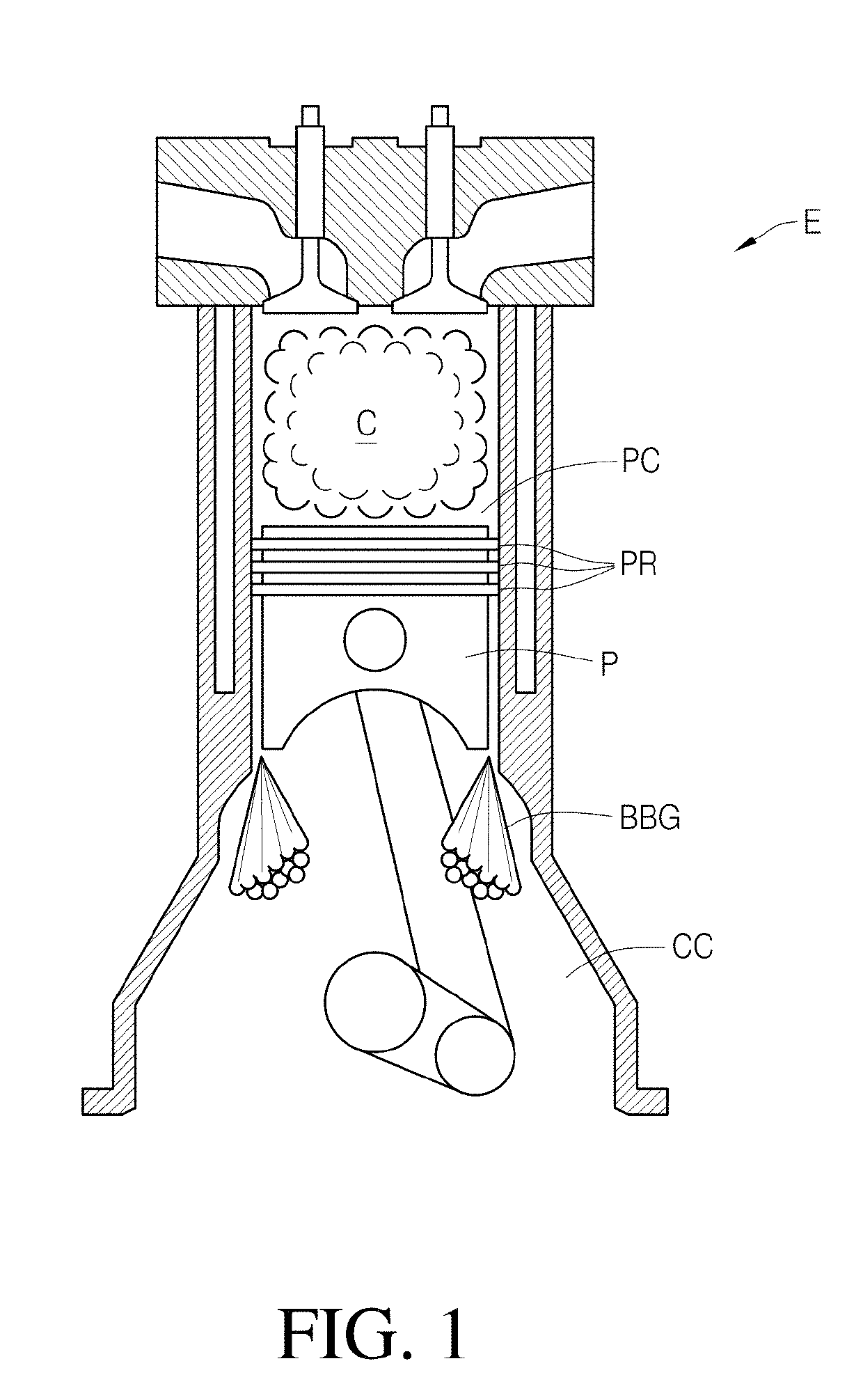
[0036]FIG. 1 illustrates the escape of blow-by gases BBG from a piston cylinder PC in an internal combustion engine E. Blow-by gases can include gases that escape from within the cylinder such as during the combustion C of fuel and the expansion of the cylinder by moving a piston P. The cylinder can be sealed by piston rings PR attached to the piston and engaged with a wall of the pist...


PUM


Abstract

A centrifugal separator for separating blow-by gases into cleaned air and liquid for recirculation through an engine.

Description

I. CROSS REFERENCE[0001]This application claims the benefit of U.S. Patent Application No. 62 / 616,231, filed Jan. 11, 2018, the entirety of which is incorporated by reference herein.II. BACKGROUNDField[0002]This disclosure generally relates to devices, systems, and methods for processing engine blow-by gases, such as by separating oil from the gases and returning the gases, and / or oils to the engine.Certain Related Art[0003]Many piston-driven internal combustion engines that see rigorous use, and / or create large amounts of power generate blow-by gases. Blow-by gases are the result of gases leaking past seals (e.g., piston rings, valve guides, and / or valve seals) in the engine and into the crankcase. The blow-by gases flow through the crankcase and eventually escape through the engine's crankcase breathing system. For example, in many cases, the blow-by gases escape the engine by traveling down channels made to drain oil from the cylinder heads. The blow-by gases typically pick-up oi...

Claims


Application Information

Patent Timeline
Patent Type & Authority Applications(United States)
IPC IPC(8): B04B5/00F01M13/04B04B13/00
CPCB04B5/005F01M13/04B04B13/00F01M2013/0422B04B15/02B04B5/12B04B7/16B04B2005/125
Inventor KUHN, JOHN WILLIAM
Owner KUHN PERFORMANCE TECH LLC
Why Eureka
Try Eureka