Method for Detecting Composition of Steel Sample by Using Multi-Pulse Laser-Induced Plasma Spectrometer

a multi-pulse laser and plasma spectrometer technology, applied in material analysis, fluorescence/phosphorescence, instruments, etc., can solve the problems of increasing the cost of the system, difficult to ensure, and the inability to achieve dual-pulse plasma excitation with maximum efficiency, so as to improve the signal-to-noise ratio, enhance the emission of spectral lines, and improve analytical sensitivity

Active Publication Date: 2019-07-18
ACAD OF OPTO ELECTRONICS CHINESE ACAD OF SCI
View PDF8 Cites 9 Cited by
  • Summary
  • Abstract
  • Description
  • Claims
  • Application Information

AI Technical Summary

Benefits of technology

[0009]The benefit of the present invention lies in a dual-pulse laser induced plasma spectral analysis device with laser pulse widths including two specifications: picosecond and nanosecond; two pulse lasers can be generated by using one pulse laser device, wherein the first pulse laser is a nanosecond laser, the second pulse laser is a picosecond laser. With the same output and focusing optical path, the two pulses can be focused on the sample to be measured at a same position. The first nanosecond laser pulse is used to irradiate the surface of the sample to produce plasma, and then the second picosecond laser pulse is used to irradiate the plasma to enhance the emission of spectral lines, so as to achieve the two-stage distribution optimization of material ablation and plasma excitation, and thus the signal-to-noise ratio and the analytical sensitivity can be effectively improved. Th...

Problems solved by technology

Currently, all the dual-pulse LIBS technologies use two nanosecond laser devices to achieve dual-pulse excitation by means of power supply controlled delay, which increases the cost of the system and needs to focus two pat...

Method used


Image

  • Method for Detecting Composition of Steel Sample by Using Multi-Pulse Laser-Induced Plasma Spectrometer
  • Method for Detecting Composition of Steel Sample by Using Multi-Pulse Laser-Induced Plasma Spectrometer
  • Method for Detecting Composition of Steel Sample by Using Multi-Pulse Laser-Induced Plasma Spectrometer

Examples


first embodiment

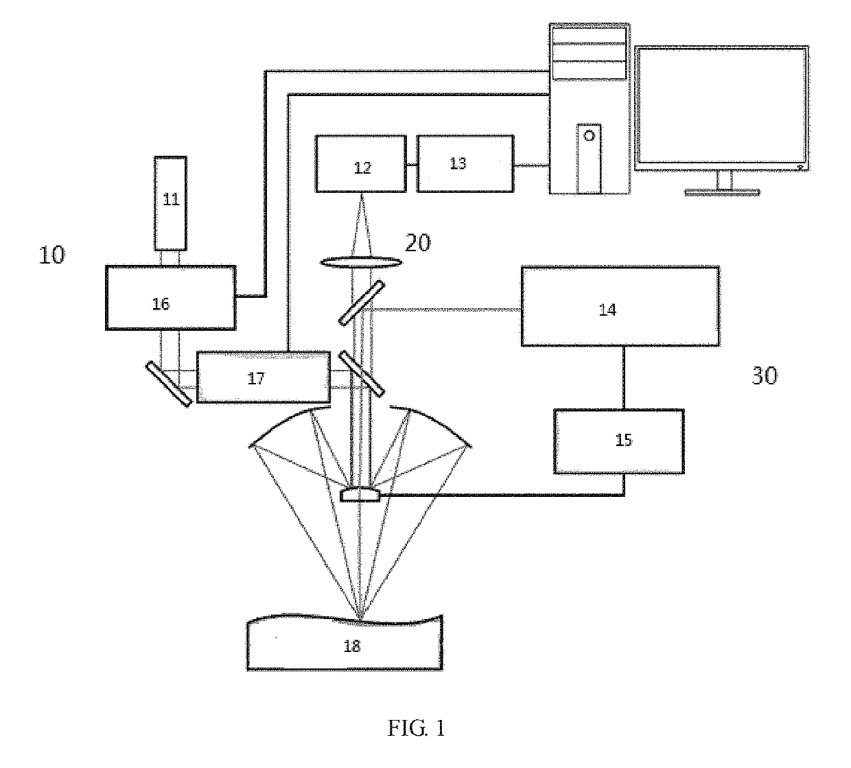
[0030]According to the present invention, provided is a laser induced plasma spectral analysis device (namely, a multi-pulse laser induced plasma spectral analysis device), wherein the spectral analysis device comprises a laser device, a laser import system, a spectrum export and collecting system, a spectroscopic system, and a spectrum receiving system; the spectrum export and collecting system comprises a spectrum export subsystem and a spectrum collecting subsystem, and the laser device and the spectrum receiving system are controlled by instructions sent by a same pulse generator; the laser device emits laser, which is focused on the sample by means of the laser import system, so that plasmas are formed on the surface of the sample to generate laser induced spectrums, and generated fluorescence is exported to the spectrum collecting subsystem by means of the spectrum export subsystem; and collected spectrums are calculated, processed, and analyzed for qualitative and quantitativ...

second embodiment

[0034]According to the present invention, provided is a method for detecting steel sample components by using the device according to the first implementation manner, wherein the method comprises the following steps:

[0035]1) output of the laser induced light source with a nanosecond pulse width is realized by the laser device in a Q-switching manner, so that the output nanosecond laser pulse is focused on the sample by means of the laser import system, and plasmas are formed on the surface of the sample;

[0036]2) output of the laser induced light source with a picosecond pulse width is realized by the laser device by means of the regeneration amplification technology, so that the output picosecond laser pulse is also focused on the sample by means of the laser import system, and spectral line emission is enhanced through the plasmas formed by irradiation of the nanosecond laser pulse, to generate laser induced spectrums with enhanced spectral lines;

[0037]3) the fluorescence from the ...

third embodiment

[0040]According to the present invention, provided is a method for detecting steel sample components by using a laser induced plasma spectral analysis device, wherein the spectral analysis device comprises a laser device, a laser import system, a spectrum export and collecting system, a spectroscopic system, and a spectrum receiving system; the spectrum export and collecting system comprises a spectrum export subsystem and a spectrum collecting subsystem, and the laser and the spectrum receiving system are controlled by instructions sent by a same pulse generator; the laser device emits laser, which is focused on the sample by means of the laser import system, so that plasmas are formed on the surface of the sample to generate laser induced spectrums, and generated fluorescence is exported to the spectrum collecting subsystem by means of the spectrum export subsystem; the collected spectrums are calculated, processed, and analyzed for qualitative and quantitative testing of elements...


PUM


Abstract

The present invention relates to a method for detecting steel sample components by using a multi-pulse laser induced plasma spectral analysis device, and in particular, to a method for detecting steel sample components by using a multi-pulse laser induced plasma spectral analysis device that includes picosecond and nanosecond laser pulse widths. A laser induced light source is a laser light source that includes nanosecond and picosecond ultrashort pulses, and one pulse laser device can be used to generate two pulse lasers, namely, a nanosecond and a picosecond laser; the two pulse lasers pass through a same output and focusing light path, so as to ensure that the two pulse lasers are focused on a same position of a sample to be detected; a surface of the sample is irradiated by using a first beam of nanosecond laser pulse to generate plasmas; subsequently, the plasmas are irradiated by using a second beam of picosecond laser pulse to enhance spectral line emission.

Description

TECHNICAL FIELD[0001]The present invention belongs to the field of detecting components of steel samples, and relates to a method for detecting components of steel sample by using a multi-pulse laser induced plasma spectral analysis device, and in particular, a method for detecting steel sample components by using a multi-pulse laser induced plasma spectral analysis device with picosecond and nanosecond laser pulse widths, and a dual-pulse laser induced plasma spectral analysis device that includes nanosecond and picosecond pulse widths of a laser induced light source and is configured to perform real-time online detection on steel sample components.BACKGROUND ART[0002]Currently, all dual-pulse LIBS technologies use two laser devices to achieve dual-pulse excitation by means of power supply controlled delay, which increases the cost of the system and needs to focus two paths of lasers respectively, and thus makes it difficult to ensure that the two paths of lasers are focused on the...

Claims


Application Information

Patent Timeline
IPC IPC(8): G01N21/71G01N33/202G01N21/64
CPCG01N21/718G01N33/202G01N21/6402G01N2201/06113G01N21/63
Inventor SUN, HUIFAN, ZHONGWEI
Owner ACAD OF OPTO ELECTRONICS CHINESE ACAD OF SCI
Why Eureka
Try Eureka