
Wireless power transmission apparatus for vehicle

a technology for power transmission apparatus and vehicle, which is applied in the direction of magnetic/electric field screening, metal casings, inductances, etc., can solve the problems of contacting the mobile terminal with achieve the effects of lowering the surface temperature of the cover, improving the adhesion and heat generation problem, and improving the heat-radiating performance of the heat-radiating cas

Active Publication Date: 2019-07-18
AMOGREENTECH CO LTD
View PDF0 Cites 14 Cited by
  • Summary
  • Abstract
  • Description
  • Claims
  • Application Information

AI Technical Summary

Benefits of technology

This patent aims to provide a wireless power transmission device for a vehicle that can lower the surface temperature of a cover and improve heat generation problems. The device includes a heat-radiating coating layer and a heat-radiating plate made of metal material, which enhances heat-radiating performance. A heat insulating layer is also used to prevent heat from transferring to the heat-radiating plate. Overall, this invention improves heat-radiating performance, adhesion, and solves the problem of heat generation in a flat coil.

Problems solved by technology

However, the outer case made of an aluminum material is effective to a certain degree of heat-radiating, but there is a limit to lowering the surface temperature of the cover contacting with the mobile terminal.

Method used


Image

  • Wireless power transmission apparatus for vehicle
  • Wireless power transmission apparatus for vehicle
  • Wireless power transmission apparatus for vehicle

Examples


exemplary example 1

[0137]65 parts by weight of a polyamide curing agent (Kukdo Chemical, G-5022) was added to 100 parts by weight of a bisphenol A type epoxy resin (YD-011) having an epoxy equivalent of 550 g / 22 parts by weight of carbon black having an average particle diameter of 150 nm and D90 of 190 nm, 3 parts by weight of a physical property enhancing component (Shanghai Tech Polymer Technology, Tech-7130) as an epoxy silane compound, 3 parts by weight of a dispersant (a mixture of isobutylaldehyde and urea 18 parts by weight of water), 18 parts by weight of methyl ethyl ketone, 28.8 parts by weight of toluene, and 285 parts by weight of cyclohexanone were mixed and stirred. After stirring, the bubbles contained in the mixture were removed and the final viscosity was adjusted to 100 to 130 cps based on 25° C. to prepare a heat radiation coating composition as shown in Table 2, and then stored at 5° C.

exemplary examples 2 to 20

[0138]Table 2, Table 3, or Table 4 were prepared by changing the kind, average particle size, particle size distribution, and kind of the coating layer forming component of the carbon-based filler as shown in Table 2, Table 3 or Table 4 was prepared.

experimental example

[0140]The heat-radiating coating compositions prepared in exemplary Examples and Comparative Examples were applied by spray coating to a thickness of 25 μm on the entire surface of a substrate made of an aluminum material (Al1050) having both sides bent in an upward direction, followed by heat treatment at a temperature of 10 minutes to form the heat radiating coating layer. The physical properties of the substrate on which the heat-radiating coating layer was formed were evaluated and shown in Tables 2 to 5 below.

[0141]1. Thermal Radiation Evaluation

[0142]A substrate having a heat-radiating coating layer formed on the center of an acrylic chamber having a size of 30 cm×30 cm×30 cm horizontally, vertically and horizontally was placed, and the temperature inside the chamber and the temperature of the substrate on which the heat-radiating coating layer was formed were adjusted to 25±0.2° C. Then, a test piece was prepared by adhering a heat source (a copper block with a ceramic heater...


PUM

PropertyMeasurementUnit
particle diameteraaaaaaaaaa

Abstract

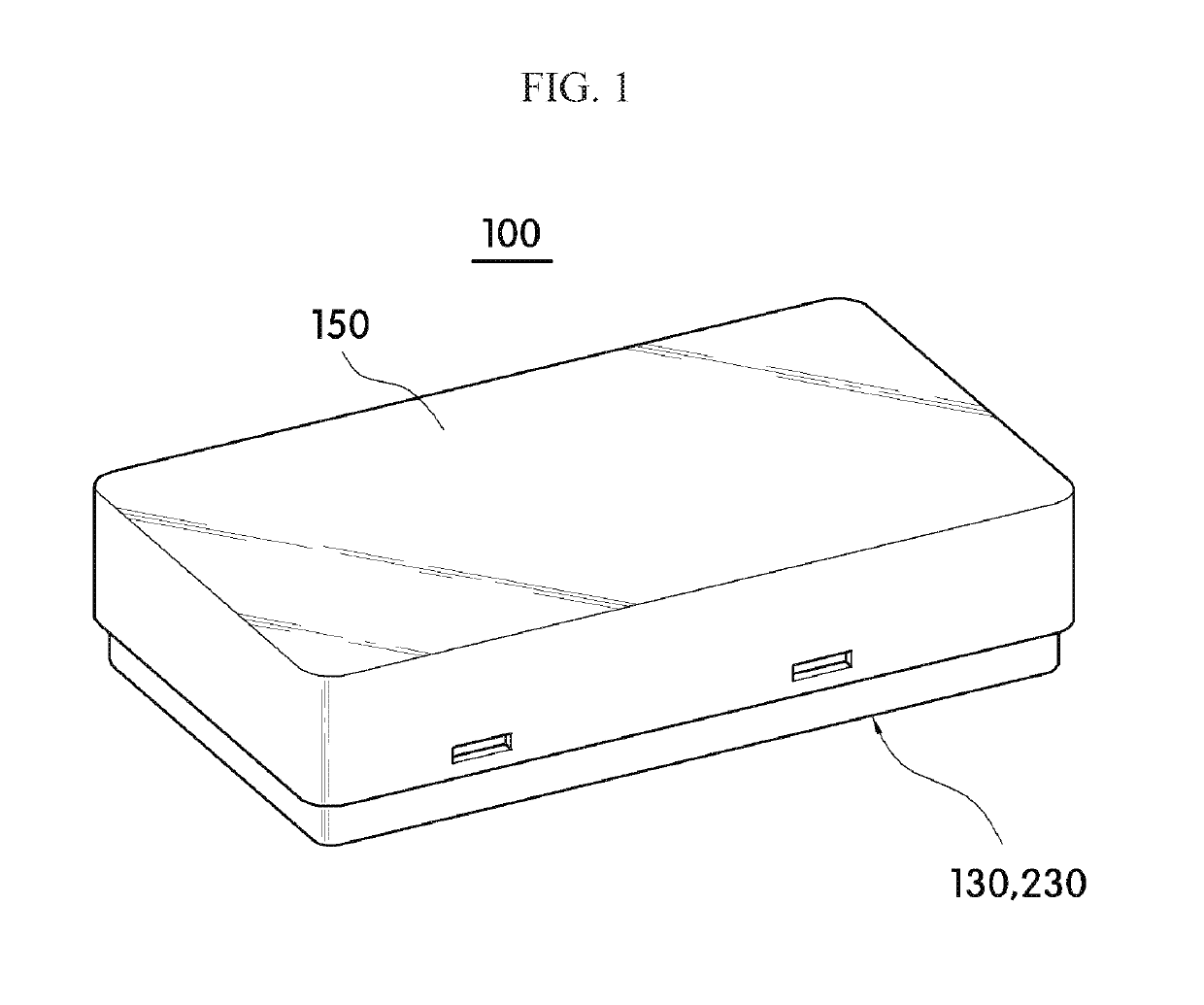
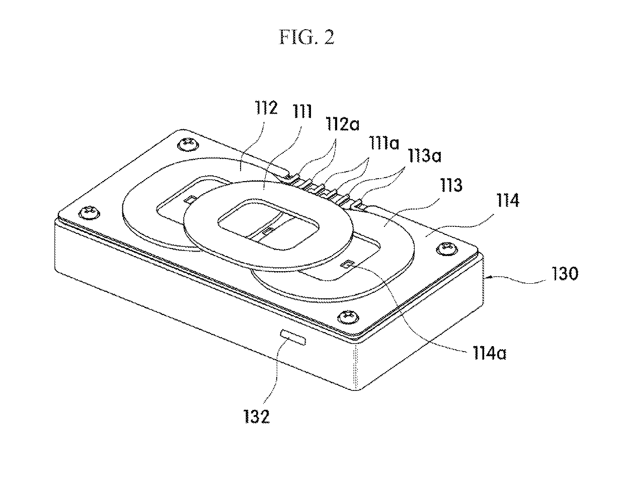
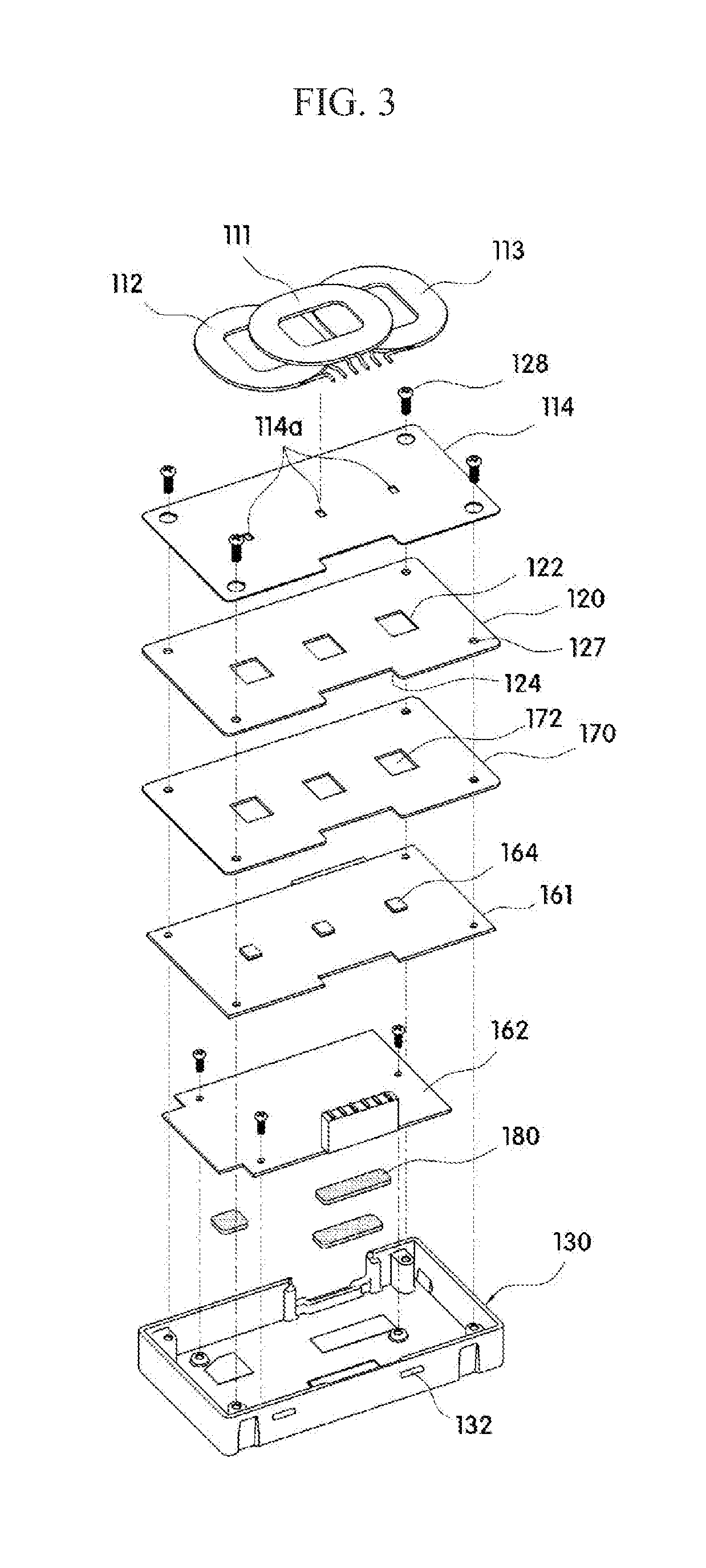
A wireless power transmission device for a vehicle is provided. The wireless power transmission device according to an exemplary embodiment of the present invention comprises: a wireless power transmission module comprising at least one flat coil for transmitting wireless power and a magnetic field shielding sheet arranged on one surface of the flat coil; a heat radiating case for radiating heat generated by a heat source, with the wireless power transmission module being coupled to one side thereof and at least one circuit board for driving the wireless power transmission module being embedded therein; a heat radiating coating layer applied to the outer surface of the heat radiating case; and a cover detachably coupled to the heat-radiating case. The wireless power transmission device for the vehicle described above may be installed or embedded within a vehicle for using in charging the main battery of a portable terminal.

Description

CROSS-REFERENCE TO RELATED APPLICATION[0001]This application claims the priority benefit of Korean Patent Application No. 10-2016-0061057 on May 18, 2016 in the Korean Intellectual Property Office, the disclosure of which is incorporated herein by reference.BACKGROUND OF THE DISCLOSUREField of the Disclosure[0002]The present invention relates to wireless power transmission, and more particularly to a wireless power transmission device for a vehicle.Description of the Related Art[0003]Wireless charging technologies which enable an electronic device to charge its battery by directly transferring and receiving power without using a power line become trends at portable electronic devices such as mobile phones, smart phones, tablet PCs, notebooks, digital broadcasting terminals, personal digital assistants (PDAs), portable multimedia players (PMPs). Recently, this wireless charging technologies expand to the charges in vehicles.[0004]A wireless power transmission device which is embedded...

Claims


Application Information

Patent Timeline
Patent Type & Authority Applications(United States)
IPC IPC(8): H01F27/02C09D7/61C09D163/00C09K5/14H02J50/10H01F38/14H01F27/36H02J50/70H01F27/28H02J7/02H05K5/03H05K7/20H05K9/00H05K5/04
CPCH01F27/025C09D7/61C09D163/00C09K5/14H02J50/10H01F38/14H01F27/365H02J50/70H01F27/2885H02J7/025H01F27/2876H05K5/03H05K7/209H05K7/20427H05K7/20509H05K9/0075H05K5/04H01F27/02H01F27/28H02J7/02H05K7/20H05K9/00H01F27/366H01F27/22H02J50/005H05K7/2039H01F27/36
Inventor HWANG, SEUNG JAE
Owner AMOGREENTECH CO LTD
Learn More