Backlight source

a backlight source and light source technology, applied in the field of display, can solve the problems of low mass production, difficult color control, and failure of qd materials, and achieve the effect of reducing the intensity of central light beams

Inactive Publication Date: 2019-07-18
HUIZHOU CHINA STAR OPTOELECTRONICS TECHNOLOGY CO LTD
View PDF6 Cites 2 Cited by
  • Summary
  • Abstract
  • Description
  • Claims
  • Application Information

AI Technical Summary

Benefits of technology

[0028]In view of the above, the side of the silicone layer, facing toward the light conversion layer, is configured with the opening corresponding to each of the LED blue-light emitting chips. The opening is configured to change the refractive direction of the central optical path and reduce intensity of central light beams. Such that, the light beams emitted from each of the LED blue-light emitting chips

Problems solved by technology

The QD material may fail due to high temperature, water vapor, and oxygen.
However, in the first protection method, the QD film requires a great amount QD material, and it is difficult to control the color in the backlight source, which may result in low mass production.
When adopting the quantum bar structure in the side-type backlight structure, the problem of alignment between the quantum bar and the LED light bar will become worse, which may result in a region where a large amount of energy is attenuated

Method used


Image

  • Backlight source

Examples


Embodiment Construction

[0031]Following embodiments of the invention will now be described in detail hereinafter with reference to the accompanying drawings.

[0032]In the drawings, the thicknesses of layers and regions may be exaggerated for clarity. Same reference numerals refer to the same components throughout the specification and the drawings.

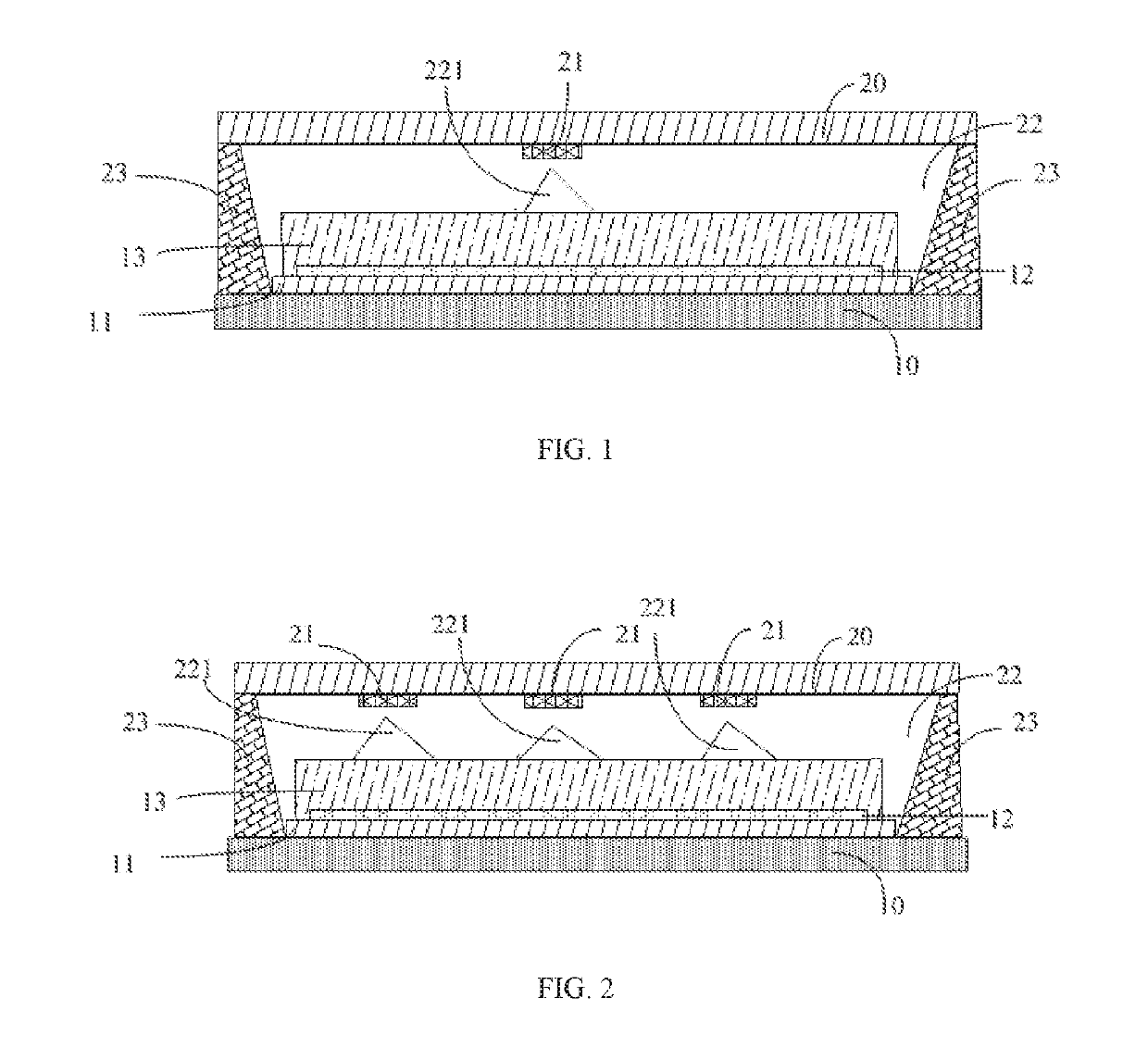
[0033]Referring to FIG. 1 and FIG. 2, the present disclosure relates to a backlight, including: a top substrate 10, a bottom substrate 20 including a flexible circuit board, a reflective layer 11, a light conversion layer 12, at least one light-emitting diode (LED) blue-light emitting chip 21, and a silicone layer 22.

[0034]Specifically, the reflective layer 11 is configured on a side of the top substrate 10, wherein the side of the top substrate 10 faces toward the bottom substrate 20.

[0035]The light conversion layer 12 is configured on a side of the reflective layer 11, wherein the side of the reflective layer 11 faces toward the bottom substrate 20, and the ligh...


PUM


Abstract

The present disclosure relates to a backlight source, including: a top substrate, a bottom substrate including a flexible circuit board, a reflective layer configured on a side of the top substrate, a light conversion layer, made of quantum dot (QD) material, configured on a side of the reflective layer, at least one light-emitting diode (LED) blue-light emitting chip configured on a side of the bottom substrate, a silicone layer configured between the light conversion layer and the bottom substrate. The opening is configured to change a refractive direction of a central optical path and to reduce an intensity of central light beams, such that light beams emitted from the at least one LED blue-light emitting chip are reflected by the reflective layer after passing through the corresponding opening to uniformly excite the QD material of the light conversion layer, and to eliminate yellow halo phenomenon.

Description

CROSS REFERENCE TO RELATED APPLICATIONS[0001]This application is a continuing application of PCT Patent Application No. PCT / CN2018 / 078802, entitled “BACKLIGHT SOURCE”, filed on Mar. 13, 2018, which claims priority to Chinese Patent Application No. 201810044654.2, filed on Jan. 17, 2018, both of which are hereby incorporated in its entireties by reference.BACKGROUND1. Technical Field[0002]The present disclosure relates to display field, and more particularly to a backlight source.2. Description of Related Art[0003]Quantum dot (QD) is also referred to as nanocrystalline, and is made of nanoparticles composed of II-VI or III-V elements. The diameter of the nanoparticles is in a range from 1 to 10 nanometers (nm).[0004]The photoelectric characteristics of the QD relate to the size and the shape. The energy band gap of the QD is inversely proportional to the size. That is, the smaller the size of the QD is, the wider the band gap will be. The wide band gap of the QD may cause the emittin...

Claims


Application Information

Patent Timeline
IPC IPC(8): H01L33/50H01L33/56H01L33/60H01L33/48
CPCH01L33/502H01L33/56H01L33/60H01L33/483G02F1/133603H01L25/0753H01L33/62H01L33/507H01L33/54G02F1/133605G02F1/133611G02F1/133614
Inventor QIU, YONGYUAN
Owner HUIZHOU CHINA STAR OPTOELECTRONICS TECHNOLOGY CO LTD
Why Eureka
Try Eureka