Systems and Methods for Detecting Magnetic Markers for Surgical Guidance

a magnetic marker and surgical guidance technology, applied in the field of surgical guidance, can solve the problems of lack of robustness, limited system, and difficulty in setting up a radioactive seed programme in all but the largest academic hospital centers, and achieve the effect of enhancing outpu

Active Publication Date: 2019-07-25
ENDOMAGNETICS LTD
View PDF0 Cites 9 Cited by
  • Summary
  • Abstract
  • Description
  • Claims
  • Application Information

AI Technical Summary

Benefits of technology

[0027]Preferably, the marker comprises less than 5 mg of LBJ material in order that the amount of material implanted in the body is minimised. The material may be provided in the form of a wire. Examples of such materials include, but are not limited to, iron-, cobalt- and nickel-rich glass-coated amorphous microwires, iron-silicon-boron based amorphous microwires, iron-cobalt based amorphous microwires, and / or bulk metallic glass wires, but any material in which a LBJ response can be excited may be suitable. The wires may be coated and / or provided within a hollow tube and / or may be deployable from an initial compact configuration to an extended, deployed configuration. Preferably, the marker is deployable from a needle having an inner diameter of less than 2 mm in order to minimize the trauma and pain associated with implanting the marker.
[0031]More preferably, the system processes one or more aspects of the harmonic response of the marker, such as the magnitude of one or more odd harmonics (eg, 3rd and 5th), even harmonics (eg. 2nd, 4th and 6th) or a combination of both or the ratios of these harmonics to each other or the fundamental frequency. Appropriate filters may be provided to enhance the sensed signals.
[0033]In a preferred embodiment of this aspect of the invention, both the drive and sense coils are provided in a handheld probe to simplify the setting up of the system for the user.
[0038]The method preferably includes measuring an aspect of the harmonic response of the marker to provide an output relating to the location of the marker. For example, this may be the amplitude of one or more odd harmonics, even harmonics or a combination of both, the ratios of these harmonics to each other or to the fundamental frequency. Appropriate filtering and processing of the signals may be provided to enhance the output provided by the method.

Problems solved by technology

However, use of radioactive materials is closely regulated, making it challenging to set up a radioactive seed programme in all but the largest academic hospital centers.
However, this system is limited by the low tissue penetration depth of IR radiation, the need for intimate tissue contact for good IR propagation, and the lack of robustness often associated with an implantable device containing antennae and electronic circuits.
The drawback with this approach is that the small RFID tag constitutes a dipole antenna which has ‘deadspots’ when approached perpendicular to the dipole axis.
This could cause confusion for surgeons using the system to localize a lesion.
Miniaturizing the RFID tag sufficiently for convenient clinical implantation is also challenging.
It has therefore proved problematic to provide a marker and detection system that possesses all the properties required for localising lesions, namely: a marker of a small size (<10 mm long); ability to deliver the marker through a small needle (eg.
These conditions make this large Barkhausen jump behaviour described in the prior art unsuitable for use as a lesion localisation marker for the following reasons:The critical length required for the large Barkhausen jump of most such materials is greater than 5-10 mm making them too large for conveniently marking small lesions which may be only a few millimetres in size.The switching field must be above a threshold in order to drive the bistable behaviour.
This limits the size of the detection coils to typically less than 20 mm diameter and thus limits the distance at which a marker can be detected.
This is undesirable for surgical guidance where in order to maximise signal to noise ratio from the very small fields being detected, it is desirable to average the signal over a number of cycles.
A further drawback of the EAS systems is the large anisotropy of the response from the marker wires, meaning that the response in the axial direction is much greater than the response in the transverse direction.
However, in surgical guidance with a handheld probe, a response that varies depending upon the direction of approach will be confusing to the user because the marker will appear to be a varying distance from the probe depending upon the orientation of approach.

Method used


Image

  • Systems and Methods for Detecting Magnetic Markers for Surgical Guidance
  • Systems and Methods for Detecting Magnetic Markers for Surgical Guidance
  • Systems and Methods for Detecting Magnetic Markers for Surgical Guidance

Examples


Embodiment Construction

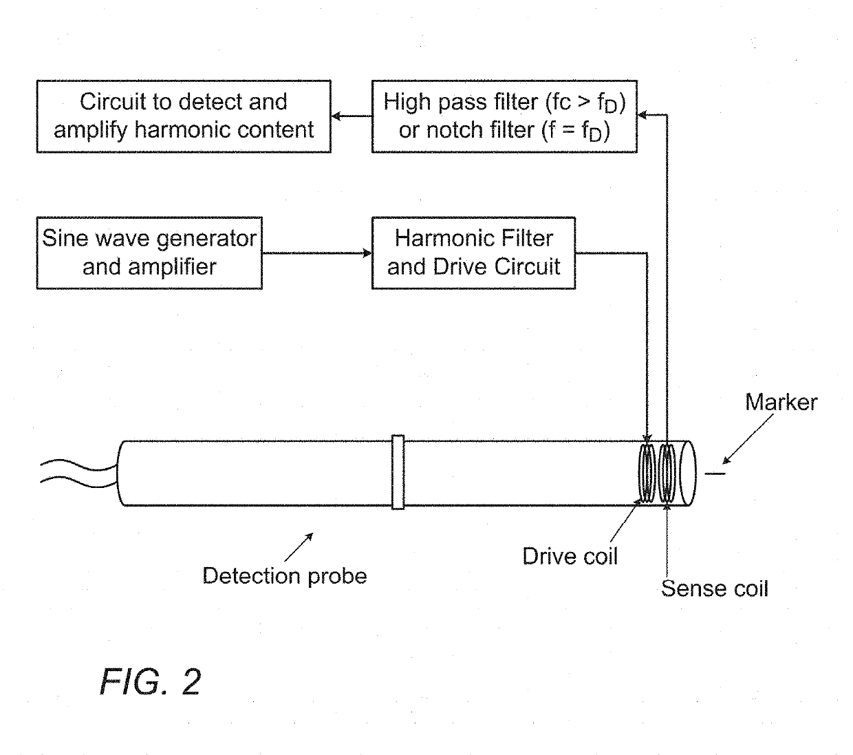
[0061]The present invention relates to a magnetic marker that can be implanted for marking a target site in the body, and subsequently be detected and localised using a handheld probe. The invention provides a detection system and method for locating the position of the implanted marker in the body.

[0062]The marker may be implanted in a site requiring marking in the body. This may, for example, be a tumour or other lesion or site of interest in soft tissue. Examples include but are not limited to benign lesions, cancerous lesions and lymph nodes. The marker may be placed in or near a lesion or multiple markers may be placed to mark the margins or perimeter of a surgical site, for example the margins of a soft tissue sarcoma.

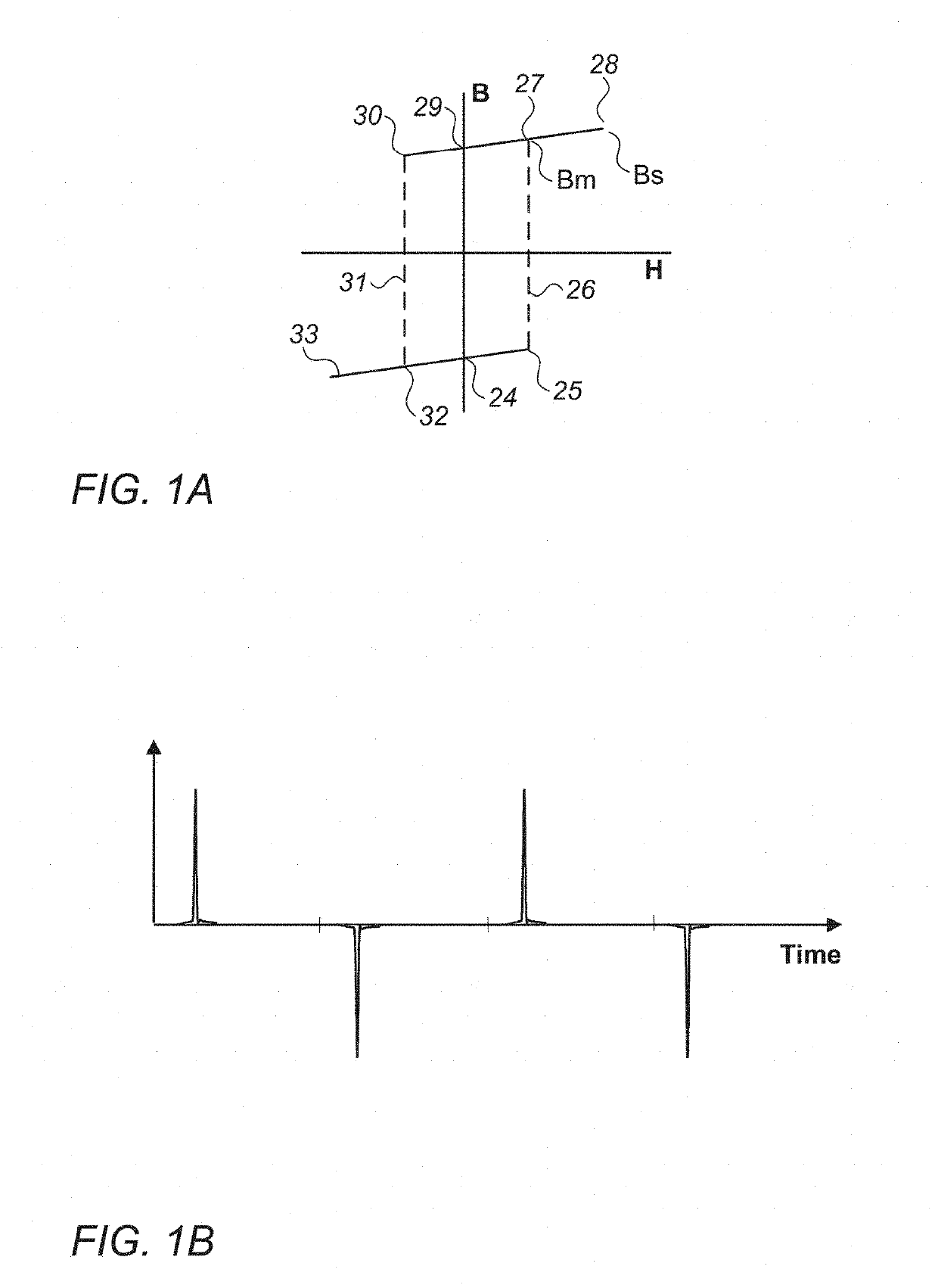
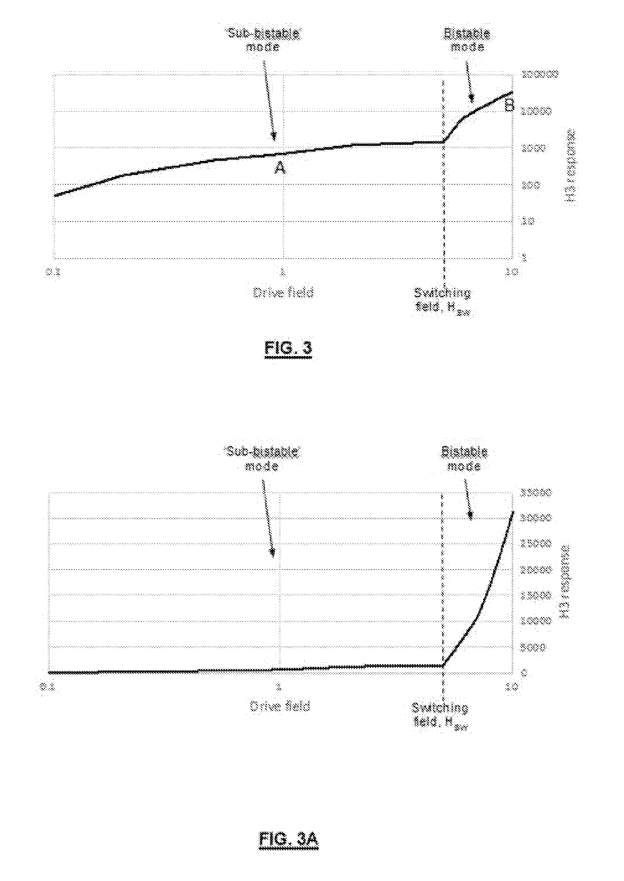
[0063]The detection system and method of the present invention utilises a different mode of excitation for LBJ materials that has not prior hereto been recognised. The inventors have surprisingly found that a different mode of excitation for LBJ materials incorpo...


PUM


Abstract

A detection system and method uses an implantable magnetic marker comprising at least one piece of a large Barkhausen jump material (LBJ). The marker is deployed to mark a tissue site in the body for subsequent surgery, and the magnetic detection system includes a handheld probe to excite the marker below the switching field for bistable switching of the marker causing a harmonic response to be generated in a sub-bistable mode that allows the marker to be detected and localised. The marker implanted may also be shorter than the critical length required to initiate bistable switching of the LBJ material.

Description

FIELD OF THE INVENTION[0001]This invention relates in general to the field of surgical guidance, more specifically to systems and methods for detecting markers that aid in locating a site in the body, for example, a lesion for surgical excision.BACKGROUND OF THE INVENTION[0002]Markers are used to guide surgeons to a region of interest during a surgical procedure, where the site of interest is not physically visible or palpable, for example a small tumour that needs to be excised. Ideally, such a marker will be deployable through a narrow gauge needle e.g. 18 g to 14 g in order to reduce trauma to the patient. Typically, such markers are less than 5 mm in length so as to be unobtrusive and to minimise trauma. The marker may be placed during a biopsy or other surgical procedure at a site of interest in the body, for example a cancer lesion. The marker is placed under imaging guidance such as ultrasound or X-ray / mammography. During subsequent surgery, the marker is detected and localis...

Claims


Application Information

Patent Timeline
Patent Type & Authority Applications(United States)
IPC IPC(8): A61B90/00A61B5/06G01D5/20
CPCA61B90/39A61B5/062G01D5/20A61B2090/3958A61B2562/0223A61B2090/3908A61B2017/00867A61B2017/00876A61B34/20A61B2034/2051A61B2090/3954A61B2090/397A61B2090/3987A61B5/064A61B2505/05A61B2090/3925A61B2090/3966A61N5/1049G01R33/1215A61B2090/3995A61N2005/1051A61B2090/3904A61B10/00
Inventor AGOSTINELLI, TIZIANOLORIMER, KEVINHARMER, QUENTIN JOHN
Owner ENDOMAGNETICS LTD
Why Eureka
Try Eureka