
Biomedical measuring devices, systems, and methods for measuring analyte concentration

Pending Publication Date: 2019-08-01
JANA CARE +1
View PDF5 Cites 3 Cited by
  • Summary
  • Abstract
  • Description
  • Claims
  • Application Information

AI Technical Summary

Benefits of technology

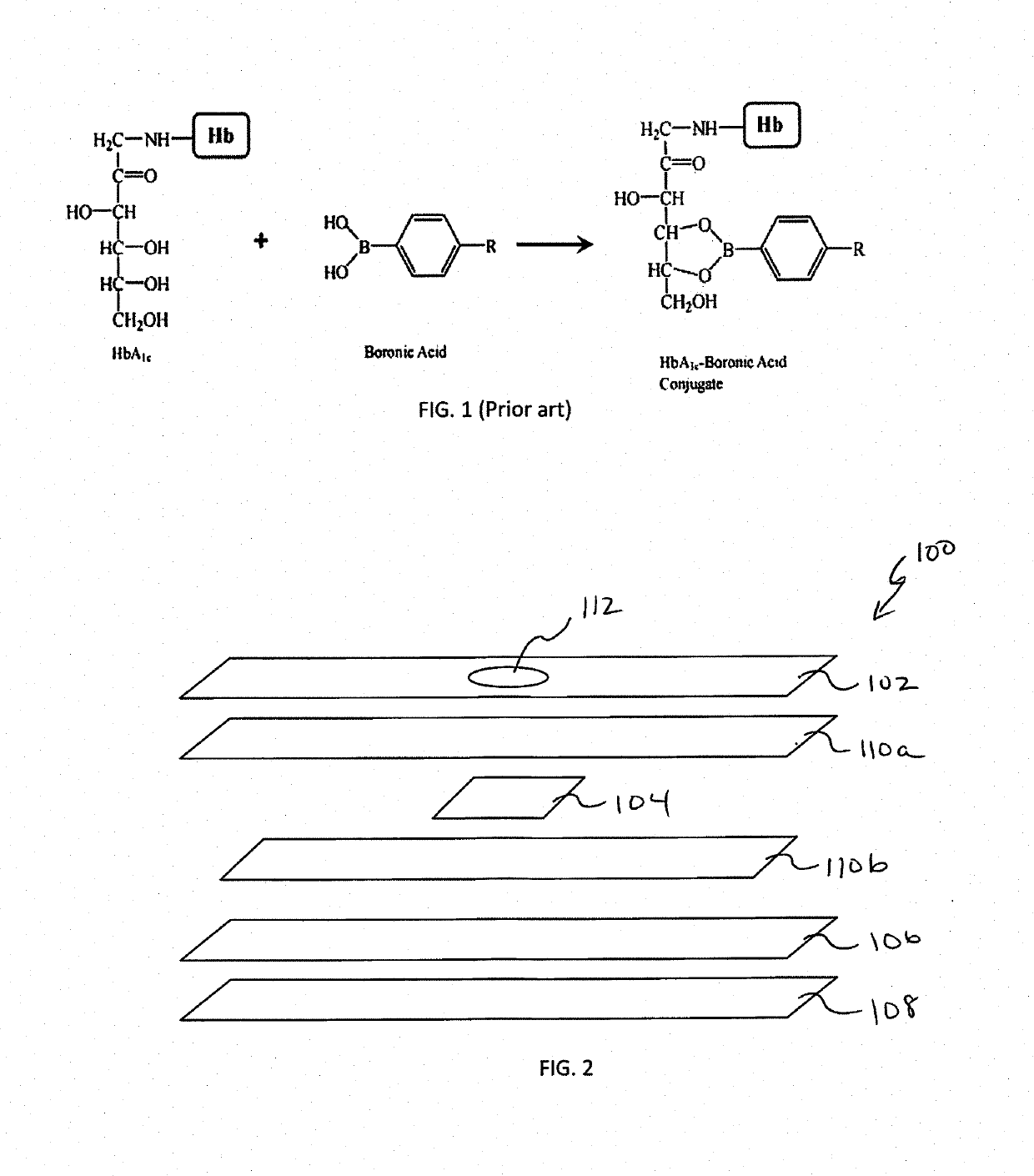
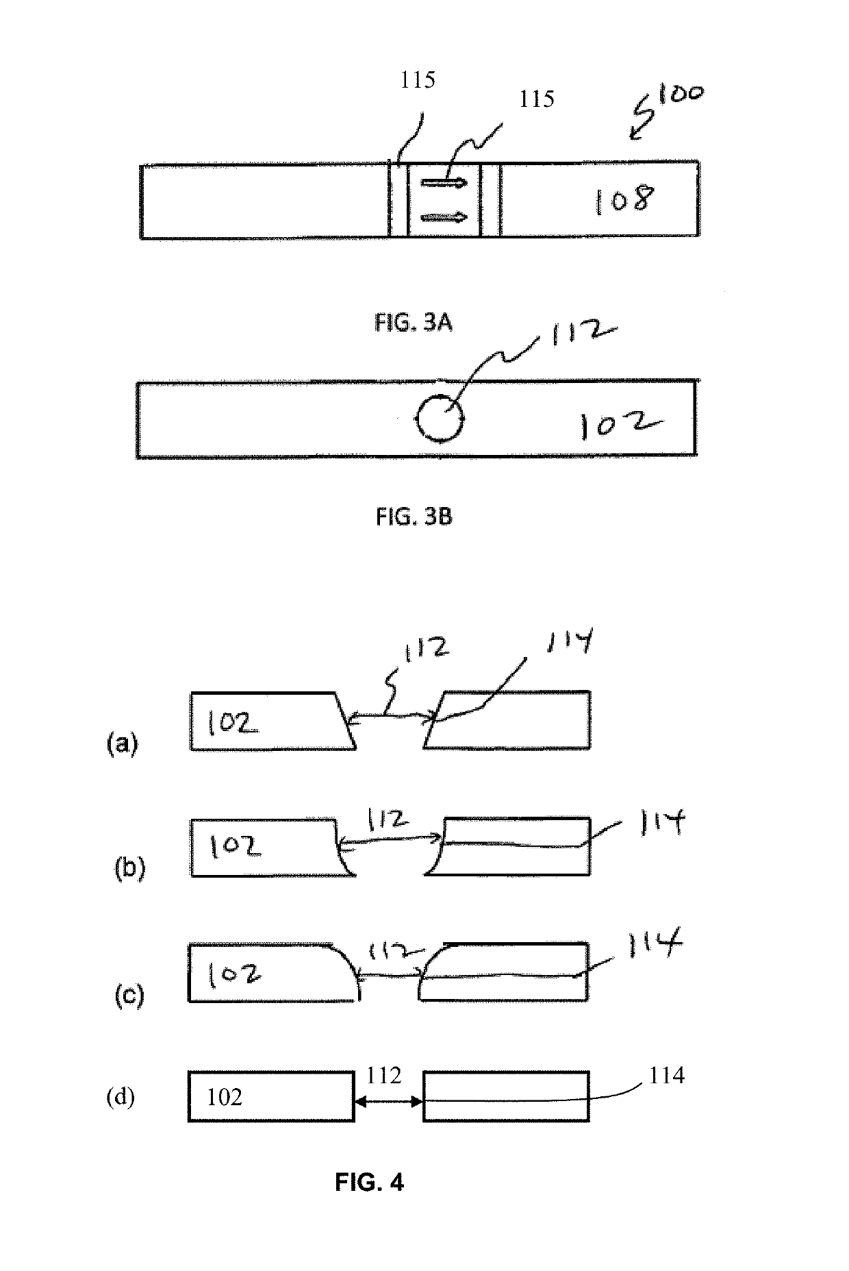
The patent describes a biomedical measuring device, called a test strip, that is simple and cost-efficient. The test strip uses a small amount of specimen to measure substances in the body. It is a quick and portable way to monitor diabetes in patients. The test strip is made of a plastic layer with a small aperture, a porous membrane to reduce background signals, an absorbent pad for fast absorption, and a barrier layer to prevent leakage. The test strip can be easily installed on a mobile device and used with an optical sensing device to collect, read, and analyze data. Overall, the technology provides a convenient and cost-effective way to measure substances in the body.

Problems solved by technology

Although sophisticated, the cost of this kind of cartridge and corresponding machine are prohibitively high.
This is a very labor consuming manual manufacturing process or requires high cost automatic machine to perform the assembly.
If the plastic housing disk does not compress the stacked material tight enough, the loaded sample will leak through the edge of the hole on the plastic disk and compromise the accuracy of the assay.
However, these technologies are high cost and have complicated manufacturing processes.
Also, these types of devices require a larger volume of reagent and specimen, and a larger optical detection unit.

Method used


Image

  • Biomedical measuring devices, systems, and methods for measuring analyte concentration
  • Biomedical measuring devices, systems, and methods for measuring analyte concentration
  • Biomedical measuring devices, systems, and methods for measuring analyte concentration

Examples


example 1

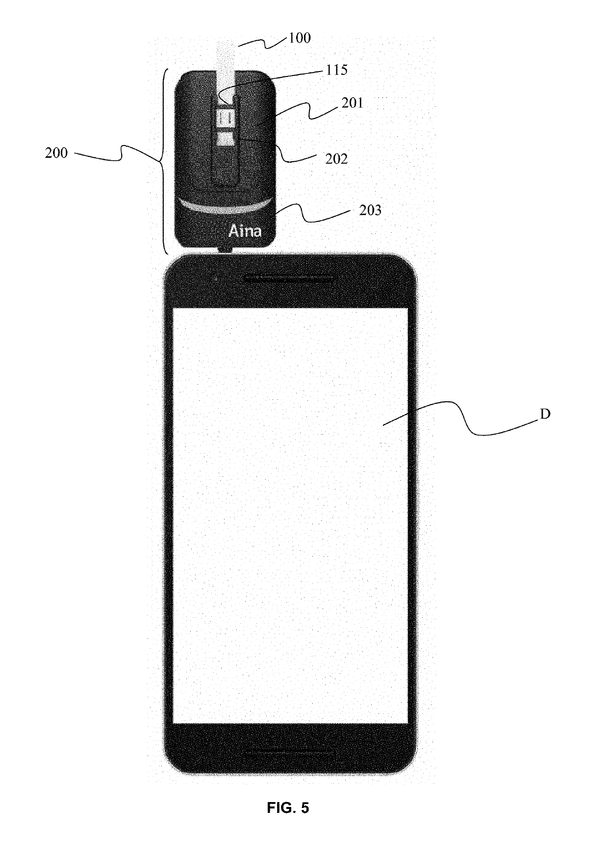
[0063]A blank test strip was first inserted into the device to obtain the background signal before the assay. The signal obtained from a blank test strip is defined as 100% reflectance. To start the assay, a 5 μl of blood sample was added to a tube containing 200 μl of lysis reagent. After sample was mixed, the tube was incubated for 2 min. 25 μl of the sample mix was applied from the tube onto the aperture of the test strip. Once the sample mix was absorbed by the test strip via the absorbent pad, 25 μl of wash buffer was applied to the aperture. Once the wash buffer was absorbed by the test strip, the test strip was inserted into the optical reader device, which in this example, included the portable POC Aina Device that is part of the Aina™ HbA1c Monitoring System available from Jana Med Tech Private Limited for Jana Care Inc. Red and Blue LED light sources contained within the device were automatically switched on by the device, and sample signal values were recorded in the phon...


PUM


Abstract

A biomedical measuring device, such as a test strip, has a simple structure, by which analyte can be measured easily using a small amount of specimen. In embodiments, the test strip generally includes a plastic first film layer having structure defining an aperture for retaining the reacting components, a porous membrane coupled to an inner-facing surface of the first film layer and configured to reduce background signal, an absorbent pad coupled to the porous membrane and first film layer to sandwich the porous membrane therebetween, the absorbent pad being configured for rapid absorption, and a plastic second film layer coupled to the absorbent pad, the second film layer being configured to provide a barrier to prevent liquid from leaking out of the test strip during use. The test strip can be easily used with an optical sensing device coupled to or containing an analyzer device (or reader device) for quickly detecting and measuring the analyte concentration. In a particular embodiment, the analyte comprises glycated hemoglobin or HbA1c, and the optical reader device is configured to determine HbA1c concentration.

Description

FIELD OF TECHNOLOGY[0001]Embodiments related generally to monitoring diabetes, and more specifically to measuring a level of glycated hemoglobin in a blood sample using a test strip and a portable optical sensing device paired to a mobile device.BACKGROUND[0002]Diabetes mellitus is a chronic disease caused by dysfunction of insulin regulation, resulting in elevated blood glucose levels and its associated complications such as diabetic retinopathy, renal failure, foot ulceration, and heart disease. Two commonly tested markers for monitoring diabetes are glucose and glycated hemoglobin (HbA1c). Long-term glucose assessment using HbA1c biomarker is advantageous because it eliminates the large fluctuations that occur daily in the blood glucose concentrations. The American Diabetes Association recently has set a ratio of HbA1c over total hemoglobin of greater than 6.5% as an indication of diabetes, while HbA1c levels of 5.7-6.4% are an indication of an increased risk for diabetes.[0003]A...

Claims


Application Information

Patent Timeline
IPC IPC(8): B01L3/00G01N33/72G01N21/78
CPCB01L3/502761G01N33/723G01N21/78B01L2300/0825B01L2300/0681B01L2300/069B01L3/5023G01N2021/7759G01N2201/0221G01N2800/042G01N2800/56G01N33/6893G01N33/526
Inventor DEPA, MICHALKUMAR, ASHOK A.JENA, SIDHANTCHEN, K.C.WANG, YUNYUAN VIVIANCHEN, STEPHEN L.
Owner JANA CARE
Learn More