Power Flow Monitoring Device for Power System, Power System Stabilization Device, and Power Flow Monitoring Method for Power System

a technology of power system and monitoring device, which is applied in the direction of testing/monitoring control system, program control, instruments, etc., can solve the problems of insufficient insufficient accuracy of monitoring function of power system, and inconvenient state estimation calculation

Active Publication Date: 2019-08-01
HITACHI LTD
View PDF0 Cites 21 Cited by
  • Summary
  • Abstract
  • Description
  • Claims
  • Application Information

AI Technical Summary

Benefits of technology

[0017]According to the present invention, in a case where the calculation of the state estimation does not converge or in a case where the accuracy is low, the case is detected as an abnormality and an alert is generated by detecting a state quantity error affecting the stability. An increase in cost due to measures such as excessive power supply control, and the like, and power failure due to measures such as excessively small power supply control, and the like are prevented by taking appropriate measures such as power supply control and the like when the alert is generated.

Problems solved by technology

In order to grasp the state of the power system, it is important to prepare a sufficient number of measurement values and to put the state of the power system in an observable state in order to solve a power equation of the power system, however, there exists a problem that the state estimation calculation may not converge, depending on a configuration of the power system and a power flow condition thereof (when there exists a section where a resistance component of a line is large; when there exists a section where s reactive power flow is large; and when, for example, voltage values of adjacent measurement values are significantly different from each other).
Further, even when the calculation converges, there exists a problem that a large deviation (residual) is generated between a measurement value and an estimation value such that reliability of an obtained estimation result (power flow state) deteriorates.
Particularly, it is conceivable that the above-mentioned problem may occur in an area where a monitoring function of the power system and accuracy thereof are insufficient.
When the reliability of the estimation result deteriorates, for example, reliability of a power system stabilization device also deteriorates.
In this case, when a wrong estimation result is inputted to the power system stabilization device and an electric control generator is determined, it is impossible to appropriately perform the electric control to prevent power failure.
Since it is not known whether or not a state estimation error affects power system stability, there exists a possibility of the power failure due to failure of appropriate measures such as power supply control, and the like.

Method used


Image

  • Power Flow Monitoring Device for Power System, Power System Stabilization Device, and Power Flow Monitoring Method for Power System
  • Power Flow Monitoring Device for Power System, Power System Stabilization Device, and Power Flow Monitoring Method for Power System
  • Power Flow Monitoring Device for Power System, Power System Stabilization Device, and Power Flow Monitoring Method for Power System

Examples


first embodiment

[0035]A first embodiment of the present invention will be hereinafter described.

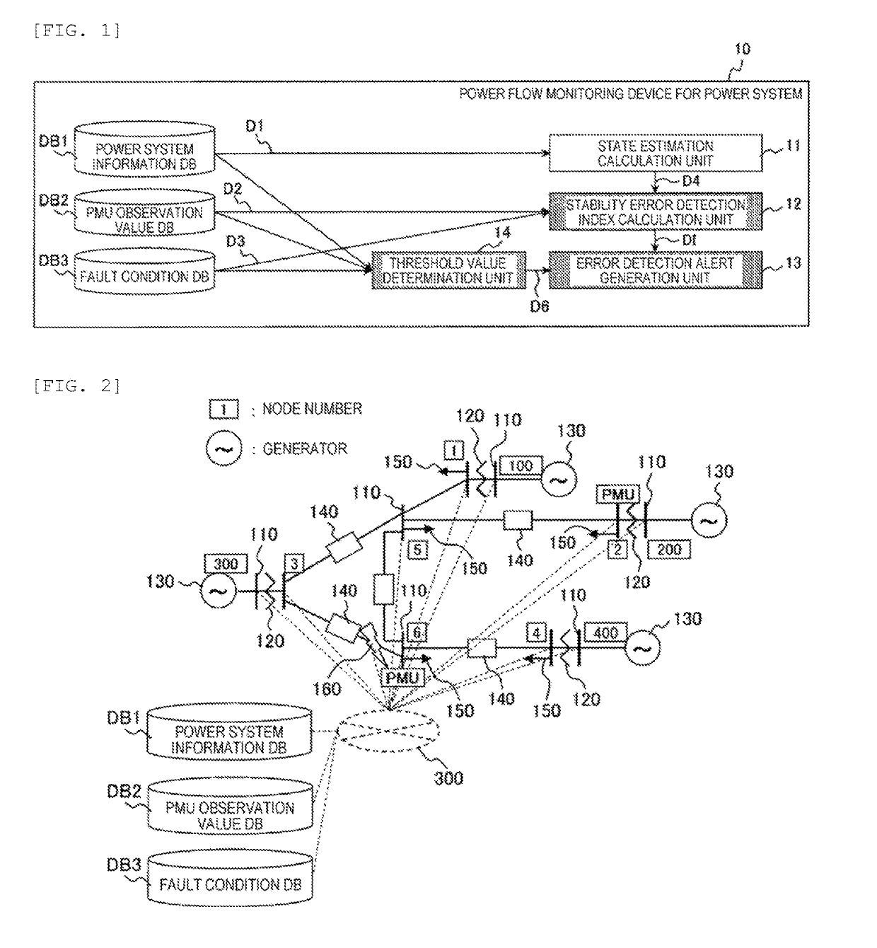
[0036]FIG. 1 is a diagram illustrating a software configuration example of a power flow monitoring device for a power system 10 to which an embodiment of the present invention is applied. The power flow monitoring device for the power system 10 is provided with a power system information database DB1, a PMU observation value database DB2, a fault condition database DB3, a state estimation calculation unit 11, a stability error detection index calculation unit 12, an error detection alert generation unit 13, and a threshold value determination unit 14.

[0037]FIG. 2 illustrates an example of a power system in which a plurality of measurement data are stored in a database via a communication network. The power system in FIG. 2 is a system in which a plurality of generators 130 and loads 150 are connected to each other via a bus (node) 110, a transformer 120, a power transmission line 140, and the like. Furth...

second embodiment

[0067]A second embodiment of the present invention will be hereinafter described. Further, the description overlapping with the content described in the first embodiment will be omitted.

[0068]FIG. 8 illustrates a software configuration example of a power flow monitoring device for a power system according to the second embodiment. The power flow monitoring device for the power system of the second embodiment illustrated in FIG. 8 is formed by adding a stability error detection index selection unit 14 to the configuration of the first embodiment. In the stability error detection index selection unit 14, when the stability error detection index calculation unit 12 calculates a plurality of stability error detection indexes, a stability error detection index having a greater value is selected from among the stability error detection indexes.

[0069]FIG. 9 is a flowchart illustrating an overall process example of the power flow monitoring device for the power system according to the secon...

third embodiment

[0072]A third embodiment of the present invention will be hereinafter described. Further, the description overlapping with the content described in the first embodiment will be omitted.

[0073]FIG. 10 is a diagram illustrating a software configuration example of a power flow monitoring device for a power system according to the third embodiment. The power flow monitoring device for the power system of the third embodiment illustrated in FIG. 10 is a power flow monitoring device for a power system in which a PMU missing data complementing unit 16 is added to the first embodiment.

[0074]In the PMU missing data complementing unit 16, when PMU observation data are not obtained for a certain fixed time or longer, or when the alert is generated or the PMU data are not obtained for less than the certain fixed time, the time series holds a previous value (any average value of several points can be used) or uses a value that predicts a change amount, thereby being regarded as a true value.

[0075...


PUM


Abstract

The purpose of the present invention is to provide a power flow monitoring device for a power system, a power system stabilization device, and a power flow monitoring method for a power system, which are highly reliable and accurate. The present invention is characterized by being provided with: a power system information database which stores measurement data obtained at a first node of the power system; a phase measurement value database which stores temporally synchronized phase measurement data obtained at a second node of the power system; a fault condition database which stores a power flow state under an assumed fault condition of the power system; a state estimation unit which estimates a state quantity of the power system using information in the power system information database as an input; a stability error detection index calculation unit which calculates a stability error detection index using, as an input, a state quantity estimation value which is an output of the state estimation unit, information of the state quantity from the phase measurement value database, and information in the fault condition database; and an error detection alert generation unit which compares the stability error detection index with a threshold value thereof and generates an alert when the stability error detection index exceeds the threshold value, wherein the magnitude of deviation of the state quantity estimation value with respect to the information of the state quantity from the phase measurement data is evaluated according to the assumed fault condition before the alert is generated.

Description

TECHNICAL FIELD[0001]The present invention relates to a power flow monitoring device for a power system, a power system stabilization device, and a power flow monitoring method for a power system for detecting a state estimation error affecting the stability of a power system.BACKGROUND ART[0002]Grasping a state of a power flow (effective power P, reactive power Q, voltage V, voltage phase δ) of a power system is not only effective for monitoring and controlling the power system, but also useful for constructing an analysis model such as power flow calculation, and the like. It is possible to predict the power system state which may occur in the future and to take stabilization measures in preparation for a fault of the power system in advance by reproducing a state close to the current power system as the analysis model. Further, generally, the state of the power system is grasped by state estimation calculation using a measurement value of an electric quantity (effective power, re...

Claims


Application Information

Patent Timeline
Patent Type & Authority Applications(United States)
IPC IPC(8): H02J13/00G05B19/042
CPCH02J13/0006G05B19/042G05B2219/2639G05B23/0235H02J3/06H02J13/00002Y04S10/30Y04S20/00Y02B90/20Y02E60/00H02J3/0012H02J13/00H02J3/00
Inventor TSUJII, YUKIKAWAKITA, KENEDWARDKUMAGAI, MASATOSHIWATANABE, MASAHIROKIKUCHI, AKIRA
Owner HITACHI LTD
Why Eureka
Try Eureka