

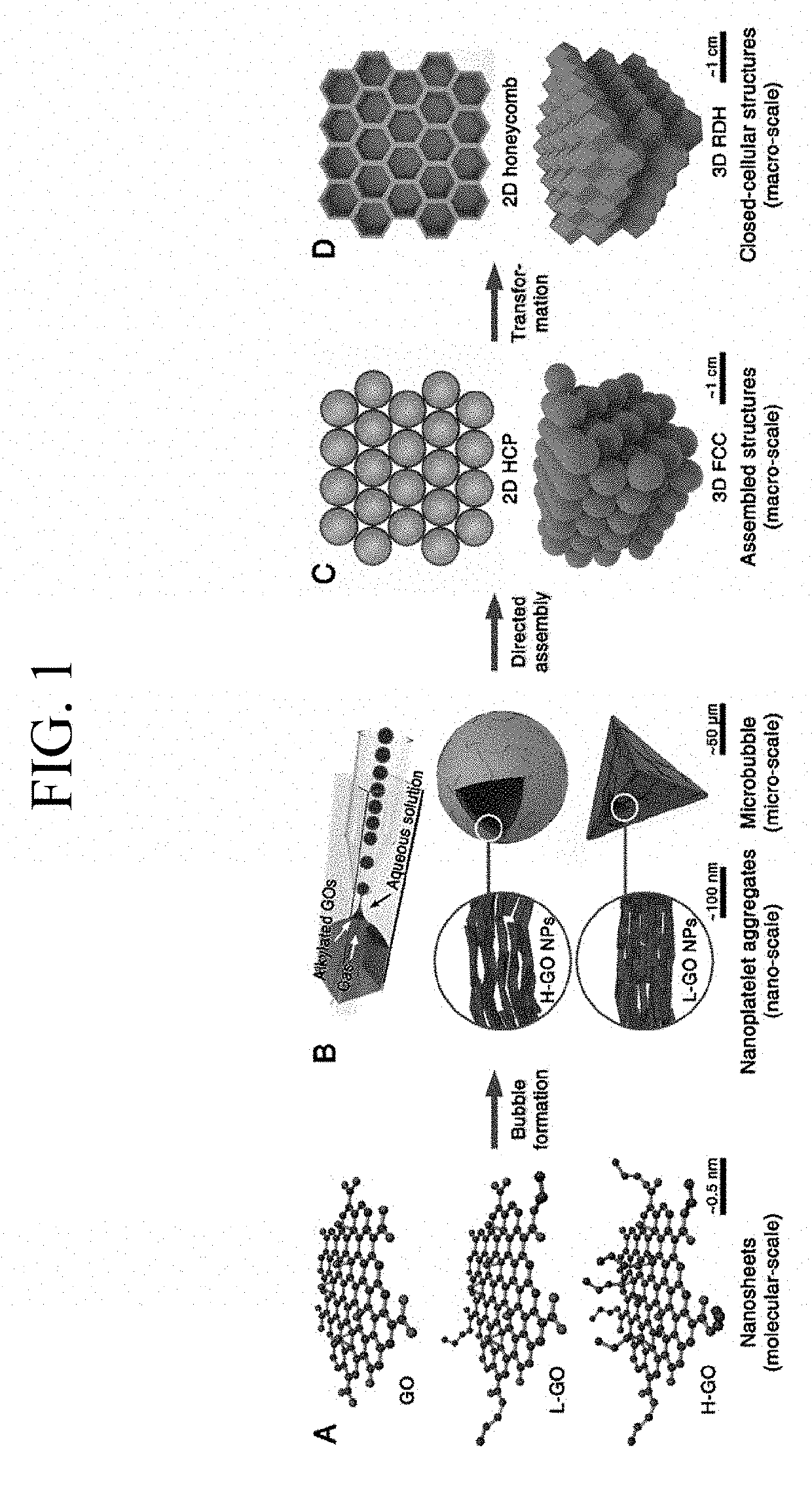
Microbubble integrated structure and method of manufacturing the same
a technology of integrated structure and microbubble, which is applied in the direction of transportation and packaging, mixing, chemical instruments and processes, etc., can solve the problems of difficult control, easy collapse of accommodating gas, and limit the size and shape of three-dimensional graphene structures, etc., to achieve ultra-high integration, light weight, and high rigidity characteristics
- Summary
- Abstract
- Description
- Claims
- Application Information
AI Technical Summary
Benefits of technology
Problems solved by technology
Method used
Image

Examples
preparation example 2b
, and Preparation Example 2B of the present invention;
[0024]FIG. 13 shows a graph of a compressive modulus and scanning electron microscope (SEM) photographs of each solid bubble before reduction (or heat treatment) and after reduction (or heat treatment) of the present invention;
[0025]FIGS. 14 to 16 are photographs showing an elasticity of the integrated structure manufactured according to Preparation Example 5, respectively; and
[0026]FIG. 17 is a view showing an example of forming microbubbles using a microfluidic system.
DETAILED DESCRIPTION OF THE EMBODIMENTS
[0027]The terminology used herein is for the purpose of describing particular embodiments only and is not intended to be limiting of the invention. The singular forms may include plural forms unless the context clearly dictates otherwise. In this application, the terms “comprises,”“having”, etc. are intended to specify the presence of stated features, steps, acts, elements, parts, or combinations thereof. However, the terms m...
preparation example 1
Bubble
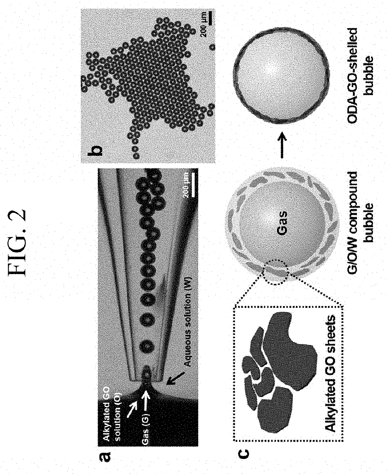
(1) Synthesis of Alkylated Graphene Oxide-1
[0099]Graphene oxide showing a negative charge was synthesized according to a modified Hummer's method with graphite. Non-exfoliated graphene oxide was removed using a centrifuge, and exfoliated graphene oxide was dispersed in water as an alkylation solvent at a concentration of 2 mg / mL. For the alkylation, 2 g of EDC was added to 400 mL of the graphene oxide solution (0.5 mg / mL) to induce a reaction of the graphene oxide with a carboxyl group to prepare an intermediate material. Subsequently, 1 g of octadecylamine (ODA) was added, such that alkylated graphene oxide-1 was prepared through an amide bond. The reaction was continued at 70° C. for 3 days, and the reactant obtained after the alkylation reaction was washed using water and ethanol several times and dried in an oven at a temperature of 70° C.
(2) Manufacture of Solid Bubbles
[0100]A glass capillary microfluidic device in which co-flow and flow-focusing were combined was prepare...
preparation example 2
Bubbles
[0103]Alkylated graphene oxide-2 was prepared according to a method substantially equivalent to the synthesis method of alkylated graphene oxide-1, except that the temperature of the alkylation reaction was lowered from 70° C. to 40° C., and the reaction time was shortened from 3 days to 1 hour.
[0104]The alkylated graphene oxide-2 was prepared, and solid bubbles according to Preparation Example 2 were manufactured by a procedure substantially equivalent to that of Preparation Example 1.
Analysis of Alkylated Graphene Oxide and Results
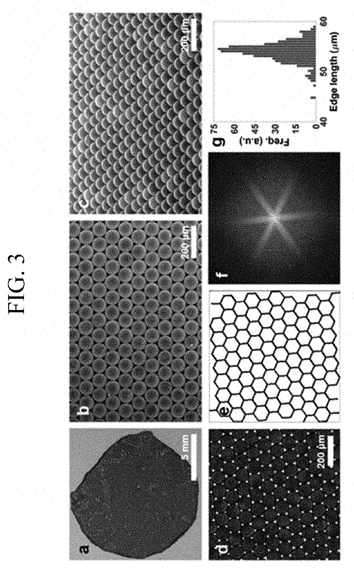
[0105]In order to compare the alkylation degree of the alkylated graphene oxide-1 (H-ODA-GO) which was used for manufacturing the solid bubbles according to Preparation Example 1 to the alkylation degree of the alkylated graphene oxide-2 (L-ODA-GO) which was used for manufacturing the solid bubble according to Preparation Example 2, the graphene oxides (GO) themselves were prepared, and then whether each of them was alkylated or not was examined t...
PUM
| Property | Measurement | Unit |
|---|---|---|
| temperature | aaaaa | aaaaa |
| temperature | aaaaa | aaaaa |
| temperature | aaaaa | aaaaa |
Abstract
Description
Claims
Application Information