
System and method for imaging underwater environments using fluid lensing

a technology of fluid lensing and underwater environment, applied in image enhancement, image analysis, instruments, etc., can solve the problems of inability to accurately assess the status and health of shallow marine ecosystems such as coral and stromatolite reefs, and no remote sensing technology can robustly image underwater objects at the cm-scale or finer, so as to improve spatial resolution and signal-to-noise properties.

Active Publication Date: 2019-08-29
NASA
View PDF0 Cites 22 Cited by
  • Summary
  • Abstract
  • Description
  • Claims
  • Application Information

AI Technical Summary

Benefits of technology

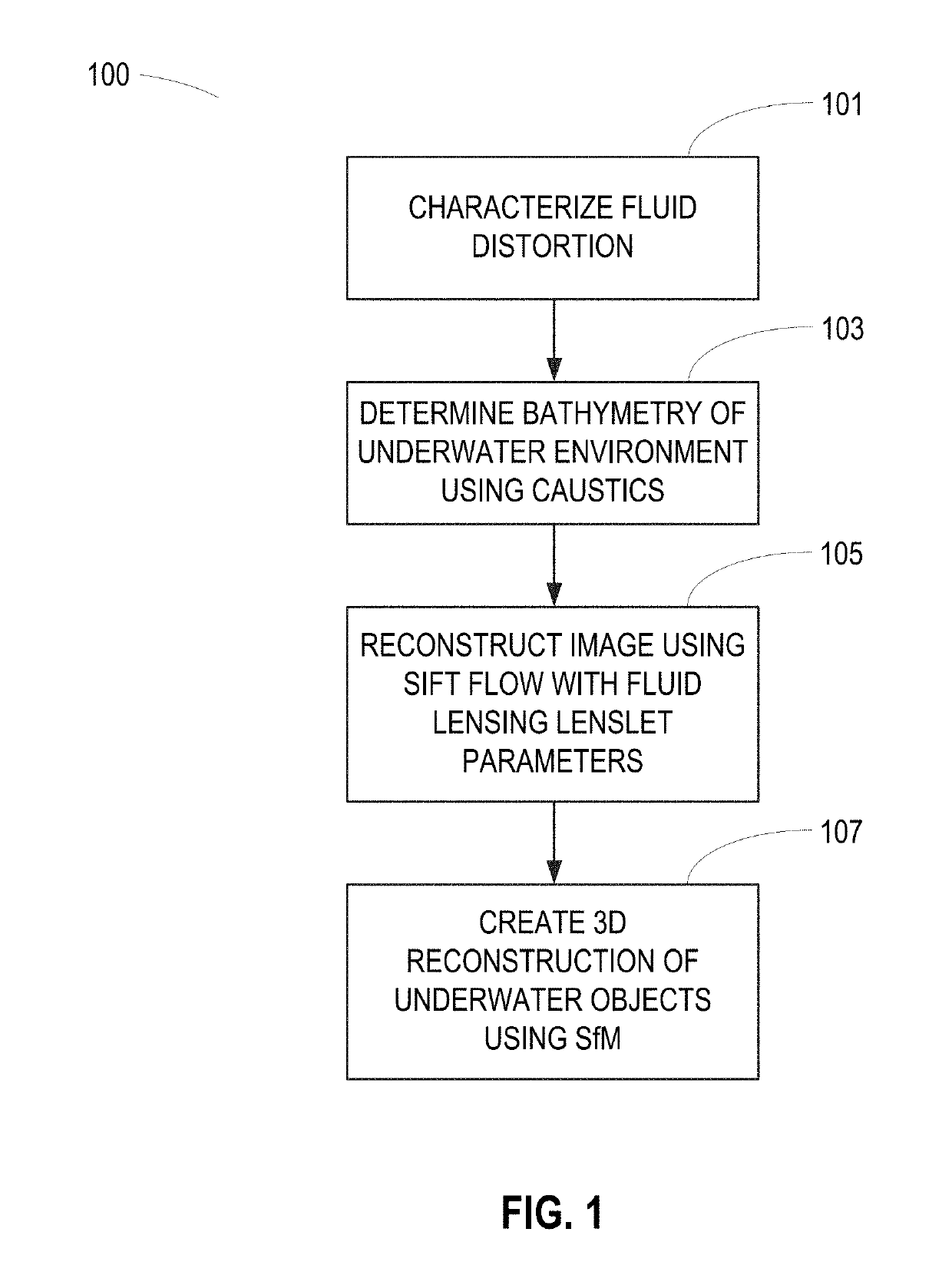
The patent describes a new method for using special lens elements to improve the resolution and accuracy of remote sensing instruments. This method introduces novel approaches for characterizing the surface of water and modeling the shape of the sea floor using caustic phenomena. It also involves a two-dimensional image reconstruction process and a three-dimensional airborne fluid lensing process for high-resolution aquatic remote sensing.

Problems solved by technology

Surface wave distortion and optical absorption of light pose a significant challenge for remote sensing of underwater environments, compounding an already profound lack of knowledge about our planet's most commonplace, biologically diverse, and life-sustaining ecosystems.
At present, no remote sensing technologies can robustly image underwater objects at the cm-scale or finer due to surface wave distortion and the strong attenuation of light in the water column, in stark contrast to modern terrestrial remote sensing capabilities.
As a consequence, our ability to accurately assess the status and health of shallow marine ecosystems, such as coral and stromatolite reefs, is severely impaired.

Method used


Image

  • System and method for imaging underwater environments using fluid lensing
  • System and method for imaging underwater environments using fluid lensing
  • System and method for imaging underwater environments using fluid lensing

Examples


Embodiment Construction

[0005]Embodiments are presented for a novel high-resolution aquatic remote sensing technique for imaging through ocean waves by harnessing the optical effects of fluid lensing lenslets and caustic bands. As visible light interacts with aquatic surface waves, time-dependent nonlinear optical aberrations appear, forming caustic bands of light on the seafloor, and producing refractive lensing that magnifies and demagnifies underwater objects. This fluid lensing phenomenon in the context of ocean waves can be exploited to image underwater environments at the cm-scale, or “reef-scale.”

[0006]Optical lensing elements that magnify, also called fluid lensing lenslets, are used to enhance the spatial resolution and signal-to-noise properties of remote sensing instruments. The process introduces a fluid distortion characterization methodology, caustic bathymetry concepts, fluid lensing lenslet homography technique, two dimensional image reconstruction process, and three dimensional airborne fl...


PUM


Abstract

Systems and methods are described for correcting distorted images captured of underwater environments. Caustics are used to provide additional illumination to underwater objects, and lenslets from ocean wave fluid lensing are used to magnify a benthic scene for enhancing the effective resolution of the images. The process introduces a fluid distortion characterization methodology, caustic bathymetry concepts, fluid lensing lenslet homography technique, two dimensional image reconstruction process, and three dimensional airborne fluid lensing process for characterizing the aquatic surface wave field, modelling bathymetry using caustic phenomena, and robust high-resolution aquatic remote sensing. Performing remote sensing using fluid lensing, also referred to as the fluid lensing process, utilizes high-frame-rate multispectral remote sensing data to remove ocean wave distortions from an image, to enhance the resolution of an image by exploiting ocean waves, and to enhance the signal strength of an image otherwise impaired by optical absorption in the water column.

Description

CROSS-REFERENCE TO RELATED APPLICATIONS[0001]This application claims the benefit of U.S. Provisional Application No. 62 / 634,803, filed on Feb. 24, 2018, the contents of which are incorporated by reference as if fully set forth herewith.ORIGIN OF INVENTION[0002]The invention described herein was made by an employee of the United States Government and may be manufactured and used by or for the Government of the United States of America for governmental purposes without the payment of any royalties thereon or therefor.FIELD OF THE INVENTION[0003]The present embodiments relate to image enhancement and correction, and more particularly, to using fluid lensing to enhance and correct distorted images captured through ocean waves of underwater environments.BACKGROUND OF THE INVENTION[0004]The optical interaction of light with fluids and aquatic surfaces is a complex phenomenon. The effect is readily observable above 71% of Earth's surface in aquatic systems, in particular, shallow marine re...

Claims


Application Information

Patent Timeline
Patent Type & Authority Applications(United States)
IPC IPC(8): G06T5/50G06T5/00G06T7/514
CPCG06T5/50G06T5/006G06T2207/20216G06T2207/30192G06T2207/10032G06T7/514G06T2207/30181G06T5/80
Inventor CHIRAYATH, VED
Owner NASA
Learn More