Heatsink mounting system to maintain a relatively uniform amount of pressure on components of a circuit board

a technology of circuit board and heatsink, which is applied in the direction of lighting, heating apparatus, and semiconductor/solid-state device details, etc., can solve the problems of component housing cracking, component overheating, and untimely contact between the heatsink and the heat generating components of the pcb

Active Publication Date: 2019-08-29
DELL PROD LP
View PDF0 Cites 13 Cited by
  • Summary
  • Abstract
  • Description
  • Claims
  • Application Information

AI Technical Summary

Benefits of technology

[0005]This Summary provides a simplified form of concepts that are further described below in the Detailed Description. This Summary is not intended to identify key or essential features and should therefore not be used for determining or limiting the scope of the claimed subject matter.

Problems solved by technology

However, rigidly mounting a heatsink to one or more heat generating components of a PCB may result in various problems.
For example, manufacturing tolerances in the height of each standoff, a warp in the PCB, or both may result in uneven contact between the heatsink and the heat generating components of the PCB.
A gap between the heatsink and a heat generating component, such as the CPU, may cause excess heat and result in the component overheating.
If the heat sink exerts too much pressure on a heat generating component, such as the CPU, the pressure may exceed the tolerances of a component, causing the component's housing to crack, and damaging the component (e.g., rendering the component inoperable).
Thus, using a fanless design that includes a large heatsink may result in a computing device that is prone to failure due to the uneven pressure applied by the heatsink on the heat-generating components.

Method used


Image

  • Heatsink mounting system to maintain a relatively uniform amount of pressure on components of a circuit board
  • Heatsink mounting system to maintain a relatively uniform amount of pressure on components of a circuit board
  • Heatsink mounting system to maintain a relatively uniform amount of pressure on components of a circuit board

Examples


Embodiment Construction

[0018]For purposes of this disclosure, an information handling system (IHS) may include any instrumentality or aggregate of instrumentalities operable to compute, calculate, determine, classify, process, transmit, receive, retrieve, originate, switch, store, display, communicate, manifest, detect, record, reproduce, handle, or utilize any form of information, intelligence, or data for business, scientific, control, or other purposes. For example, an information handling system may be a personal computer (e.g., desktop or laptop), tablet computer, mobile device (e.g., personal digital assistant (PDA) or smart phone), server (e.g., blade server or rack server), a network storage device, or any other suitable device and may vary in size, shape, performance, functionality, and price. The information handling system may include random access memory (RAM), one or more processing resources such as a central processing unit (CPU) or hardware or software control logic, ROM, and / or other type...


PUM


Abstract

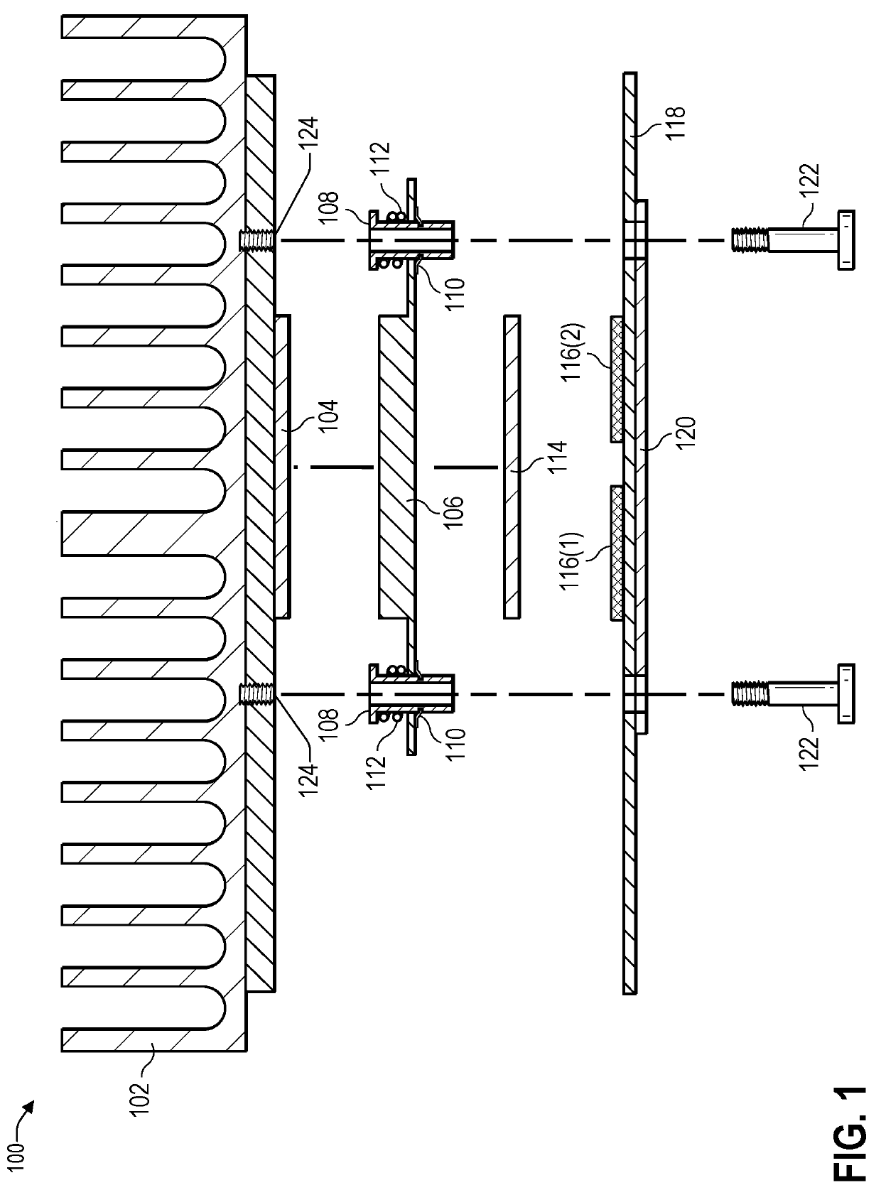
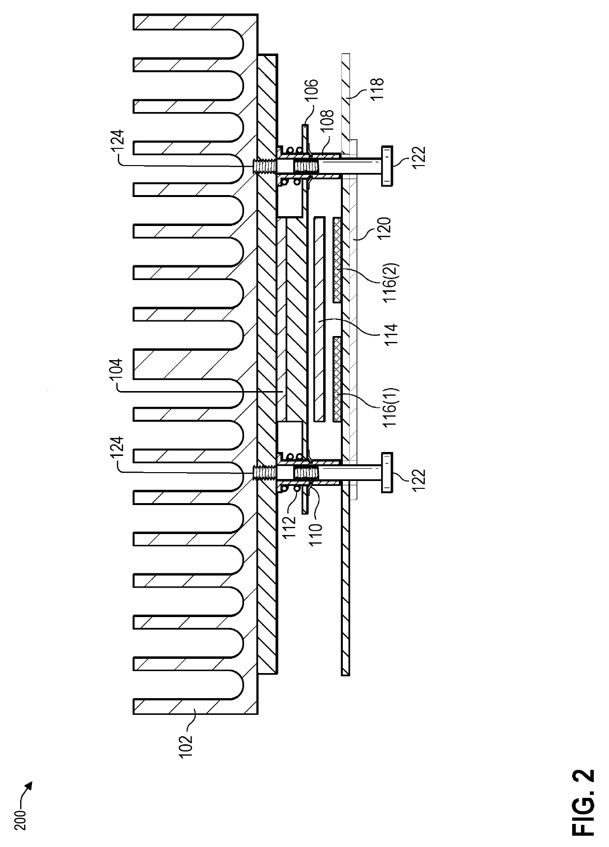
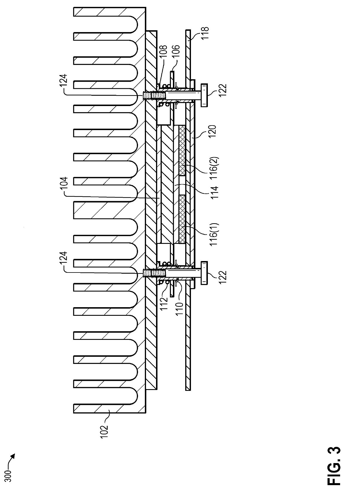
In some examples, a computing device may include a heatsink, a thermal spreader, a first thermal pad located between the heatsink and the thermal spreader, a circuit board comprising a plurality of components, and a second thermal pad located between the thermal spreader and the circuit board. A plurality of standoffs may be located between the heatsink and the circuit board. Each standoff of the plurality of standoffs may pass through a corresponding spring of a plurality of springs and pass through a corresponding mounting hole of a plurality of mounting holes in the thermal spreader. Each screw of a plurality of screws may engage with a corresponding standoff of the plurality of standoffs. The plurality of springs may cause the thermal spreader and the second thermal pad to a relatively uniform amount of pressure to each component of the plurality of components.

Description

BACKGROUND OF THE INVENTIONField of the Invention[0001]This invention relates generally to computing devices and, more particularly to mounting a heatsink to one or more heat-generating components of a circuit board in a manner in which the heatsink is rigidly mount mounted to the circuit board while allowing the heatsink to float and maintain approximately a same amount of contact and pressure with the heat-generating components.Description of the Related Art[0002]As the value and use of information continues to increase, individuals and businesses seek additional ways to process and store information. One option available to users is information handling systems. An information handling system generally processes, compiles, stores, and / or communicates information or data for business, personal, or other purposes thereby allowing users to take advantage of the value of the information. Because technology and information handling needs and requirements vary between different users o...

Claims


Application Information

Patent Timeline
Patent Type & Authority Applications(United States)
IPC IPC(8): H05K1/02G06F1/20F28F3/02
CPCH01L23/4006H01L2023/4087H05K1/0203G06F1/20F28F2275/20H05K2201/066F28F3/02H01L25/072F28D2021/0029H01L23/433
Inventor HE, QINGHONGHUANG, HOU-CHUN
Owner DELL PROD LP
Why Eureka
Try Eureka