Method and apparatus to dispense fluid onto a target area of a surface

a surface and target area technology, applied in the field of methods and, can solve the problems of reducing the effectiveness of the spatial sensing device, affecting the ability to monitor a field of view, and reducing the ability to perform dynamic object detection

Active Publication Date: 2019-09-12
UUSI NARTRON
View PDF0 Cites 19 Cited by
  • Summary
  • Abstract
  • Description
  • Claims
  • Application Information

AI Technical Summary

Benefits of technology

[0002]Spatial sensing devices, such as cameras, radars, lidars, etc., that may be disposed on a vehicle have lenses or other outer surface portions that serve to separate and thus protect sensing elements from external elements. Such protection may include protection from impingement of water, snow, mud, road salt, dust and other airborne elements. When elements precipitate onto lenses or other outer surface portions, they can cloud or otherwise reduce efficacy of the spatial sensing device, and thus affect its ability to monitor a field-of-view. One result can include delaying or otherwise reducing an ability to perform dynamic object detection employing information that is captured by the spatial sensing device. On a vehicle employing autonomous operation, reduction in an ability to dynamically detect objects or perform another sensing function may affect a capability of the autonomous operation, which may lead to disablement of the autonomous function until the lens or outer surface portion is cleaned.SUMMARY

Problems solved by technology

When elements precipitate onto lenses or other outer surface portions, they can cloud or otherwise reduce efficacy of the spatial sensing device, and thus affect its ability to monitor a field-of-view.
One result can include delaying or otherwise reducing an ability to perform dynamic object detection employing information that is captured by the spatial sensing device.
On a vehicle employing autonomous operation, reduction in an ability to dynamically detect objects or perform another sensing function may affect a capability of the autonomous operation, which may lead to disablement of the autonomous function until the lens or outer surface portion is cleaned.

Method used


Image

  • Method and apparatus to dispense fluid onto a target area of a surface
  • Method and apparatus to dispense fluid onto a target area of a surface
  • Method and apparatus to dispense fluid onto a target area of a surface

Examples


first embodiment

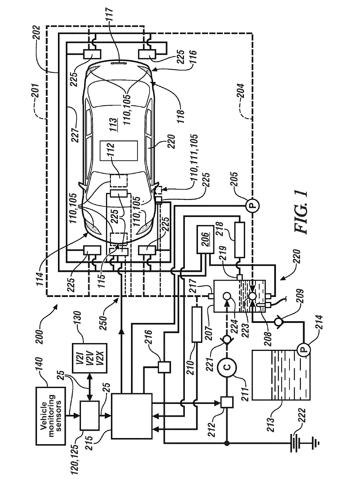
[0044]the fluid dispensing system 200 including a first fluidic distribution system 250 is shown with reference to FIG. 1 and FIGS. 4-1, 4-2, and 4-3, and includes the pressure vessel 207, which is fluidly connected to the compressed air source 211. In one embodiment, the pressure vessel 207 includes a liquid reservoir portion, with a liquid port that fluidly connects via the first fluidic distribution system 250 to distribute liquid to each of the mixing valves 225 and an air port 217 that fluidly connects via the first fluidic distribution system 250 to distribute pressurized air to each of the mixing valves 225. A heat source 208 may be disposed in the pressure vessel 207 to heat any fluid disposed therein. Alternatively, the heat source 208 may include engine or transmission coolant, battery pack coolant, or solar energy collector that is thermally coupled to the liquid or air of the system to transfer heat. In one embodiment, the compressed air source 211 is a stand-alone air c...

second embodiment

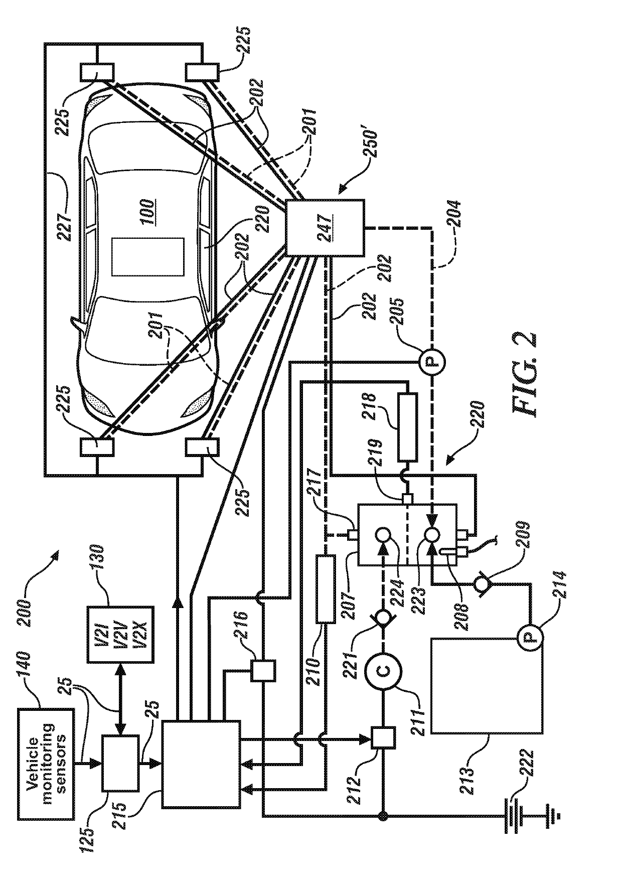
[0050]FIG. 2 schematically shows the fluid dispensing system 200, wherein the pressurized fluidic supply system 220 fluidly connects via a second fluidic distribution system 250′ to the mixing valves 225. In this embodiment, the first fluidic conduits 201 and second fluidic conduits 202 fluidly connect a manifold 247, which distributes air and liquid individually to each of the mixing valves 225 via first fluidic conduits 201 and second fluidic conduits 202.

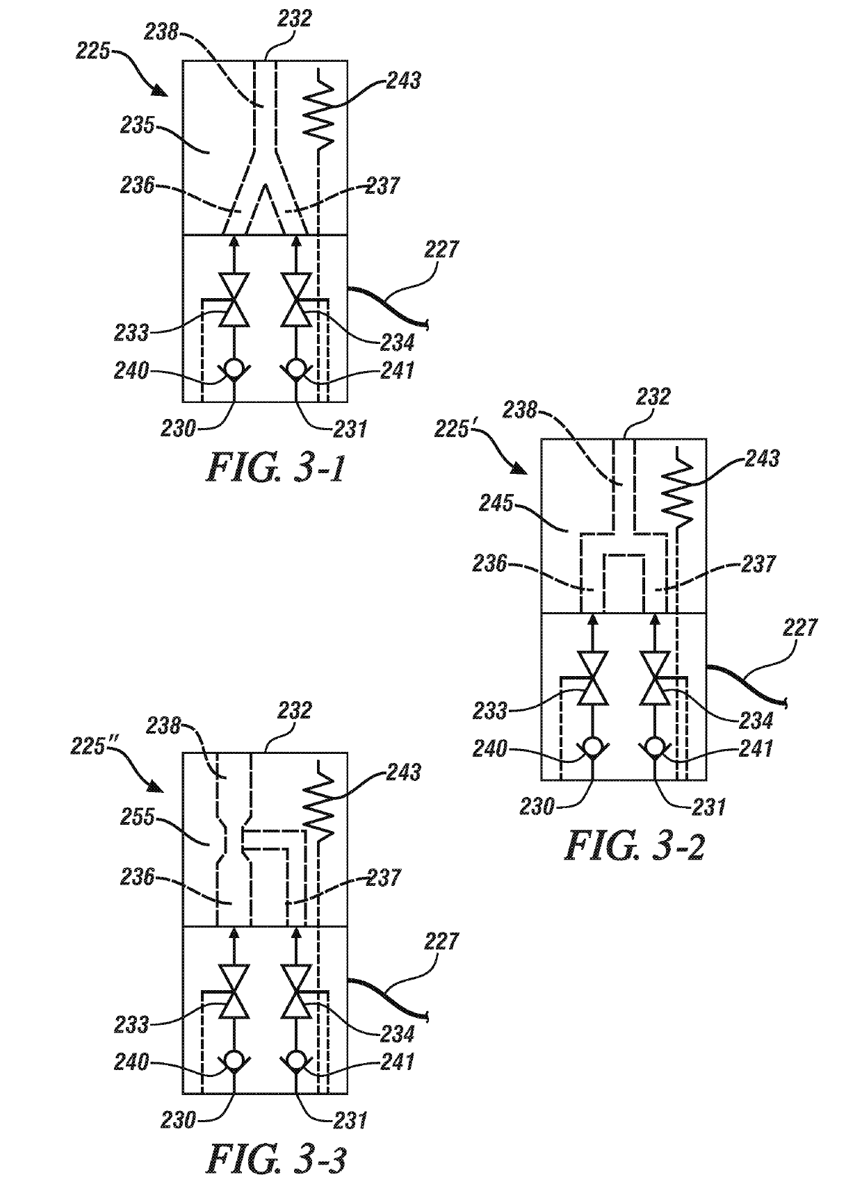
[0051]FIG. 3-1 schematically shows a first embodiment of the mixing valve 225, which includes a mixing portion 235 that is fluidly connected to a first valve conduit 236 and a second valve conduit 237. The mixing portion 235 terminates at an outlet orifice 232 that is proximal to one of the aforementioned target areas on the vehicle 100. The first valve conduit 236 includes a first inlet 230 that is fluidly connected to a first check valve 240 that is disposed upstream of a first control valve 233, which is fluidly connected to t...

third embodiment

[0054]FIG. 3-3 schematically shows the mixing valve 225″, which includes a mixing portion 255 that is fluidly connected to the first valve conduit 236 and the second valve conduit 237. In this embodiment, the mixing portion 245 is configured such that the first valve conduit 236 and the second valve conduit 237 join together in a venturi configuration to effect mixing of the pressurized liquid and air into the single conduit 238 that terminates at the outlet orifice 232.

[0055]The term “controller” and related terms such as control module, module, control, control unit, processor and similar terms refer to one or various combinations of Application Specific Integrated Circuit(s) (ASIC), electronic circuit(s), central processing unit(s), e.g., microprocessor(s) and associated non-transitory memory component(s) in the form of memory and storage devices (read only, programmable read only, random access, hard drive, etc.). The non-transitory memory component is capable of storing machine...


PUM


Abstract

A device for dispensing liquid onto a target area of a vehicle surface is described, and includes a mixing valve that is in communication with a pressurized fluidic supply system via a fluidic distribution system, and a controller. The mixing valve includes an outlet orifice that is disposed proximal to the target area, and the mixing valve includes first and second valve conduits that are fluidly connected to the outlet orifice via a mixing portion. The first valve conduit includes a first control valve, and the second valve conduit includes a second control valve. The fluidic distribution system includes a first fluidic conduit and a second fluidic conduit. The controller is operatively connected to the fluidic supply system, and the first and second control valves.

Description

CROSS-REFERENCE TO RELATED APPLICATIONS[0001]This application claims the benefit of U.S. Provisional Patent Application No. 62 / 639,440, filed on Mar. 6, 2018, the disclosure of which is hereby incorporated by reference.INTRODUCTION[0002]Spatial sensing devices, such as cameras, radars, lidars, etc., that may be disposed on a vehicle have lenses or other outer surface portions that serve to separate and thus protect sensing elements from external elements. Such protection may include protection from impingement of water, snow, mud, road salt, dust and other airborne elements. When elements precipitate onto lenses or other outer surface portions, they can cloud or otherwise reduce efficacy of the spatial sensing device, and thus affect its ability to monitor a field-of-view. One result can include delaying or otherwise reducing an ability to perform dynamic object detection employing information that is captured by the spatial sensing device. On a vehicle employing autonomous operatio...

Claims


Application Information

Patent Timeline
Patent Type & Authority Applications(United States)
IPC IPC(8): B60S1/56B08B3/10B05B1/30B60S1/48B60S1/50B60S1/52B60S1/54B60S1/60B60R1/06
CPCB60S1/481B60S1/603B60S1/52B60S1/488B60R1/0602B08B3/10B60S1/54B05B1/3013B60S1/487B60S1/50B60S1/56B60S1/486B05B7/0483B05B7/168
Inventor AGROTIS, DEMETRIS A.SHANK, DAVIDCOX, EDWARD J.
Owner UUSI NARTRON
Why Eureka
Try Eureka