Dielectric-heating bonding film and bonding method using dielectric-heating bonding film

a dielectric heating and bonding film technology, applied in the direction of film/foil adhesives without carriers, film/foil adhesives, metal-working apparatuses, etc., can solve the problems of dielectric heating to carbonize a adhered portion and/or the adherends, difficult to apply dielectric heating at an accurate position or adhere the adhered portions at the correct position, etc., to achieve favorable balance

Active Publication Date: 2019-09-19
LINTEC CORP
View PDF0 Cites 0 Cited by
  • Summary
  • Abstract
  • Description
  • Claims
  • Application Information

AI Technical Summary

Benefits of technology

[0042]The B component in a form of zinc oxide can exhibit predetermined exothermic effect during the dielectric heating even being blended in the adhesive component (the A component) at a relatively small amount.
[0043]In addition, zinc oxide can be uniformly dispersed in the adhesive component (the A component), providing a favorable balance between the transparency of the dielectric welding film and the weldability during the dielectric heating.

Problems solved by technology

However, the dielectric heating disclosed in Patent Literatures 1 and 2, in which a considerable amount of the conductive material such as carbon black (CB) is blended in the adhesive to prepare the adhesion layer composition, is likely to cause electric breakdown during the dielectric heating to carbonize a adhered portion and / or the adherends.
In addition, vertical alignment of the adherends is difficult due to the color of the resultant adhesion layer composition (i.e. perfectly opaque black (visible light transmissivity: 0%)).
Accordingly, it is difficult to apply the dielectric heating at an accurate position or adhere correct portions.

Method used


Image

  • Dielectric-heating bonding film and bonding method using dielectric-heating bonding film
  • Dielectric-heating bonding film and bonding method using dielectric-heating bonding film

Examples


first exemplary embodiment

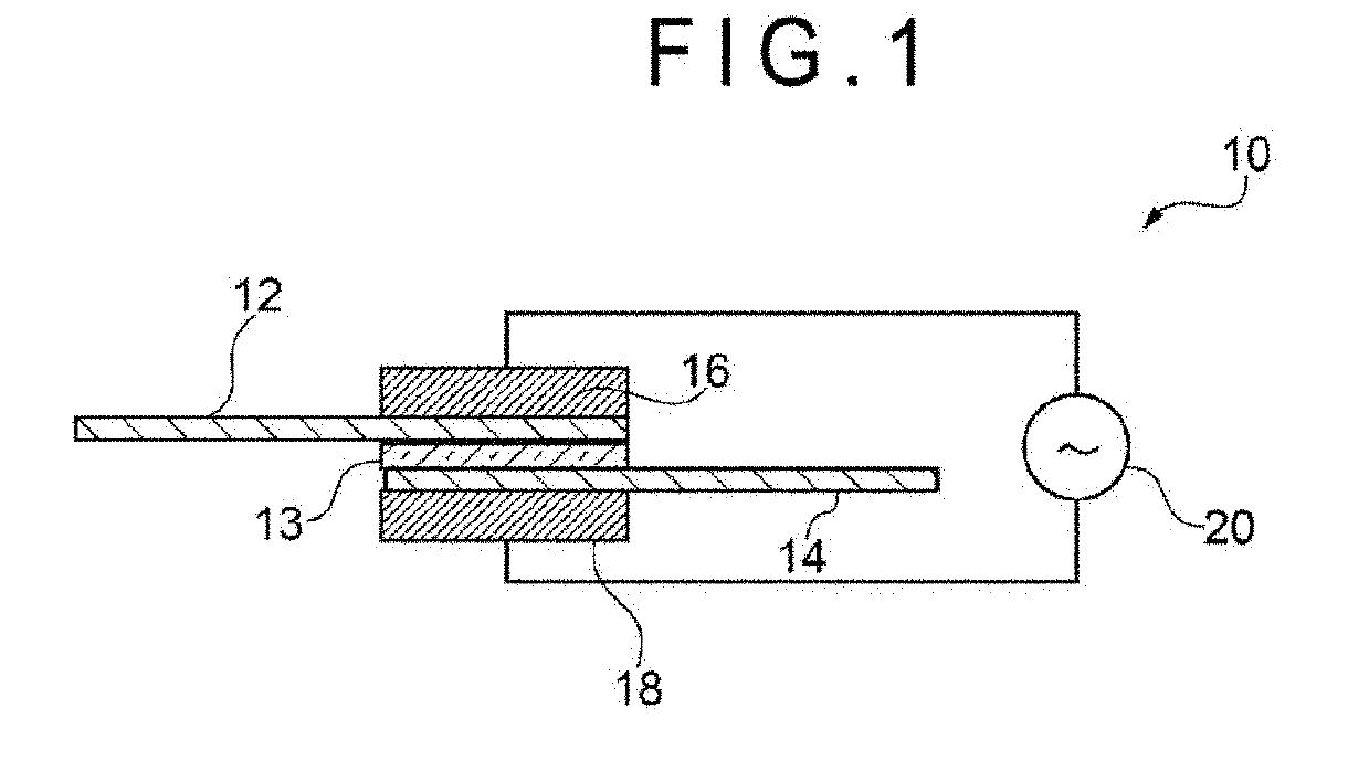
[0057]A dielectric welding film according to a first exemplary embodiment is configured to weld a pair of adherends of the same material or different materials through dielectric heating, the dielectric welding film including:

[0058]a thermoplastic resin as an A component and a dielectric filler as a B component,

[0059]the dielectric welding film satisfying conditions (i) and (ii) below:[0060](i) a melting point or softening point measured in accordance with JIS K 7121 (1987) being in a range from 80 to 200 degrees C.; and p0 (ii) heat of fusion measured in accordance with JIS K 7121 (1987) being in a range from 1 to 80 J / g.

[0061]The components, properties and the like of the dielectric welding film according to the first exemplary embodiment will be specifically described below.

1 Components of Dielectric Welding Film

(1) A Component

Type

[0062]The thermoplastic resin as the A component, whose type is not limited, is, for instance, preferably at least one of a polyolefin resin, an olefin...

second exemplary embodiment

[0132]A welding method according to a second exemplary embodiment uses a dielectric welding film for welding a pair of adherends of the same material or different materials through dielectric heating, the dielectric welding film including a thermoplastic resin as the A component and a dielectric filler as the B component and satisfying the conditions (i) and (ii) below:[0133](i) a melting point or softening point measured in accordance with JIS K 7121 (1987) being in a range from 80 to 200 degrees C.; and[0134](ii) heat of fusion measured in accordance with JIS K 7121 (1987) being in a range from 1 to 80 J / g, the method including the following steps (1) and (2) of:[0135](1) holding the dielectric welding film between a pair of adherends; and[0136](2) applying the dielectric heating on the dielectric welding film held between the pair of adherends with a dielectric heater at a high-frequency output ranging from 0.1 to 20 kW and a high-frequency wave application time of 1 second or mo...

example 1

1. Preparation of Dielectric Welding Film

[0152]100 parts by mass of a random polypropylene resin as the A component (Prime Polypro F-744NP manufactured by Prime Polymer Co., Ltd., melting point: 130 degrees C., referred to as A1-1 in Table 1) and 156 parts by mass of zinc oxide (LPZINC11 manufactured by Sakai Chemical Industry Co., Ltd., mean particle size: 11 μm, referred to as B1 in Table 1) were weighed and each put into a vessel.

[0153]Subsequently, as shown in Table 1, the A component and B component were preliminarily blended and then were fed into a hopper of a biaxial extruder of 30 mm diameter, where the components were melted and kneaded at a cylinder set temperature in a range from 180 to 200 degrees C. and a die temperature of 200 degrees C. to obtain granular pellets.

[0154]Then, the obtained granular pellets were put into a hopper of a uniaxial extruder provided with a T-die, and a 400-μm thick film-shaped molten kneaded product was extruded from the T-die at a cylinder ...


PUM

PropertyMeasurementUnit
frequencyaaaaaaaaaa
mean particle sizeaaaaaaaaaa
frequencyaaaaaaaaaa

Abstract

A dielectric welding film capable of achieving a tight welding through a short period of dielectric heating, and a welding method using the dielectric welding film are provided. The dielectric welding film is configured to weld a pair of adherends of the same material or different materials through dielectric heating, the dielectric welding film including a thermoplastic resin as an A component and a dielectric filler as a B component and satisfying the conditions (i) and (ii):
  • (i) a melting point or softening point measured in accordance with JIS K 7121 (1987) is in a range from 80 to 200 degrees C.; and (ii) heat of fusion measured in accordance with JIS K 7121 (1987) is in a range from 1 to 80 J/g.

Description

TECHNICAL FIELD[0001]The present invention relates to a dielectric welding film, and a welding method using the dielectric welding film.[0002]Specifically, the present invention relates to a dielectric welding film, which is usable for adherends of different types and is capable of providing a large adhesivity through a relatively short period of dielectric heating (sometimes referred to as high-frequency dielectric heating hereinafter), and a welding method using the dielectric welding film.BACKGROUND ART[0003]In order to weld a plurality of typically hard-to-bond adherends (i.e. difficult to be bonded), it has been recently proposed that, for instance, a welding process such as dielectric heating, induction heating, ultrasonic welding or laser welding is performed with an adhesive produced by blending a heat-generating material in a predetermined resin.[0004]According to a proposed welding method by dielectric heating among the above, an adhesive blended with carbon black (CB), si...

Claims


Application Information

Patent Timeline
Patent Type & Authority Applications(United States)
IPC IPC(8): B29C65/04B29C65/50B29C65/42C09J123/26C09J11/04C09J129/14C09J131/04C09J167/00C09J177/00C08K3/22
CPCC09J11/04C09J129/14C08K2201/005C09J167/00B29C65/50C08K3/22B29C65/04C09J131/04C08K2003/2296C09J123/26B29C65/425C08K3/14C09J177/00C09J123/00C09J123/10C09J125/04C09J201/00H05B6/46H05B6/64B23K13/00C09J7/10C09J2423/00C09J2423/106C08K2003/2237C09J5/06C09J2467/00C09J2301/304C09J2301/408C09J2301/312C09J2451/00C09J7/00C09J123/12B29C65/40C09J7/35C09J9/00C09J2203/326C09J2423/10H01B3/441H01B17/56H05B6/50C09J2301/416
Inventor ISHIKAWA, MASAKAZU
Owner LINTEC CORP
Why Eureka
Try Eureka