Single-cell encapsulation and flexible-format module architecture and mounting assembly for photovoltaic power generation and method for constructing, inspecting and qualifying the same

a photovoltaic and single-cell technology, applied in the direction of renewable energy source integration, semiconductor devices, climate sustainability, etc., can solve the problems of nuclear power requiring large capital investment, each alternative approach has drawbacks, and the module format and characteristics are not flexibl

Inactive Publication Date: 2019-10-24
TESSOLAR
View PDF0 Cites 0 Cited by
  • Summary
  • Abstract
  • Description
  • Claims
  • Application Information

AI Technical Summary

Benefits of technology

[0008]This invention overcomes disadvantage of prior art by providing a system and method that alleviates, for example, the breakage and degradation of PV cells in manufacturing lines; the lack of flexibility in module format and characteristics; and the performance limitations of current PV module architectures. Illustratively, a photovoltaic (PV) device is provided. The device is constructed using Single Cell Encapsulation (SCE), according to various embodiments and the assembly of the individually encapsulated cells into a module. Illustratively, by encapsulating individual PV cells of various dimensions in a multilayer structure comprising a bottom layer, a layer of encapsulant, the PV cell, another layer of encapsulant and the top layer, many benefits including flexible architecture, automated manufacturing, low cell breakage, cell and structure decoupling, etc., can be realized.
[0013]The sub-structure, frame or framework of the FMA can incorporate features that ease the installation of PV modules in the field, on a roof or on any structure. The sub-structure can also allow for factory pre-assembly of modules, integrating a large number of cells, cells oriented in preferred direction or orientation or any other customized form for specified functions.
[0014]In various illustrative embodiments, a platform or assembly seat for fabrication of a solar PV module is provided. This platform includes a sub-structure and one or more solar cells. The solar cells are illustratively interconnected to provide electrical power and the sub-structure is constructed and arranged to provide physical protection and support to individual ones of the solar cells. Illustratively, the solar cells are each individually encapsulated and the sub-structure includes an integral joint assembly to join a mounting structure or to adjacent sub-structures. The sub-structure can include a composite material. The composite material can comprise a thermoplastic, and thermoplastic can include PET and / or glass fibers. The glass fibers can be continuous and / or can be chopped, with an aspect ratio of length-to-diameter greater than approximately 10. The materials of the sub-structure can be constructed and arranged to be resistant to ultraviolet light and / or flame retardant. Illustratively, the sub-structure can be constructed by a low-cost thermoplastic process, and can be positioned at a location corresponding to a back sheet of a conventional PV module. The joint assembly can be constructed and arranged for direct mounting to roof integrated hardware. The joint assembly can be constructed and arranged to provide a direct connection to pylons of a ground mounted system. The sub-structure can also be constructed and arranged to allow factory pre-assembly of multiple modules into larger systems that contain predetermined structural support and to allow for assembly of a multi-module onto field-installed footings. Illustratively, the solar cells can be individually, optimally inclined for a specified location and connected so that a center of gravity of the module enables mounting thereof onto a single axis tracker. Between 2 and 2,000 solar cells (per-module, by way of non-limiting example) can be assembled and interconnected. Note, further, that the number of cells-per-module and overall number of modules is highly variable and not limited by a specific parameter. The sub-structure can be constructed and arranged to enclose or attach wiring and / or to allow for integration of electrical storage devices. The sub-structure can include an integrated junction box, an integrated micro inverter, cell-level electronics and / or integrated busbars and tabs, constructed and arranged to interconnect to the solar cells. The sub-structure is also illustratively constructed and arranged to be optimized so as to reduce weight thereof while maintaining structural integrity thereof. The arrangement can be free of exposed metallic components. In embodiments, the sub-structure is ungrounded and constructed and arranged to reduce potential induced degradation of PV modules in the ungrounded state. Also, the sub-structure can be constructed and arranged to optimize packing density of modules for shipping cost reduction.
[0015]A method for encapsulating solar cells is provided in illustrative embodiments. This method includes the step of providing a source of silicone encapsulant, applying silicone to the solar cells in an amount that efficiently generates a layer of encapsulant on each of the solar cells. In this manner, an amount of silicone utilized for the encapsulant provides an economically viable production process. The step of applying the silicone reduces glass bowing during encapsulation of each of the solar cells, and can include encapsulating individual ones of the solar cells. Illustratively, a thickness of silicone between an edge of each of the solar cells and an outer edge of the encapsulant layer is no more than approximately 1.5 mm so as to allow cells to be packaged within 3 mm of each other in a module. A plurality of electrically interconnected solar cells can be constructed according to the above method for encapsulating. The solar cells can include an edge exclusion that is no more than 5 mm. Illustratively, the silicone provides a high transparency so as to optimize light transmission to the solar cells. The solar cells and connections between solar cells can be constructed and arranged to withstand string voltages of at least (e.g.) 1500 V. The photovoltaic module can be constructed and arranged to reduce degradation of the module electricity generation potential over time.
[0016]In illustrative embodiments, a method for continuous encapsulation of solar cells is also provided. This method includes the steps of arranging solar cells so as to provide for the inspection and qualification (steps of inspecting and qualifying) of each individual one of the solar cells, and encapsulating the arranged solar cells so that, after encapsulation, and before integration of encapsulated solar cells into a PV module, each of the encapsulated solar cells can be inspected and qualified. The inspection and qualification can include performing an electroluminescence test and / or a solar simulation (IV) test. Results of the inspection and qualification can provide a decision on Maximum Open Circuit Voltage, Closed Circuit Current, Fill Factor and efficiency of the encapsulated cell. The results of the inspection and qualification can also provide a decision on utility of the encapsulated cell and / or enable sorting of the encapsulated solar cells based upon performance thereof. The continuous encapsulation can comprise a lean manufacturing process in illustrative embodiments. The method can further include constructing the PV module to contain the encapsulated solar cells, so as to exhibit similar response to light to enable a manufacturing yield with a statistically higher performing module with a tighter distribution. The encapsulant can comprise silicone. Additionally, the method can include connecting tabs of the solar cells to cell busbars using a solderless process. The illustrative solderless process can utilize advanced light capturing ribbons. The method can also include utilizing conductive adhesive to electrically connect the ribbons to the solar cells. In various embodiments, the method can include electrically connecting the ribbons to the solar cells using direct connections. The method can include the use of solar cells with substantially reduced silver content or the elimination of busbars on the cells. The method is generally adapted to reduce manufacturing-induced defects in the solar cells. The arrangement can include a Non-Fluorinated back sheet and the solar cells can include individual glass having chamfers on edges thereof constructed and arranged to optimally refract light falling between the solar cells.

Problems solved by technology

These supplies are limited and their combustion causes atmospheric pollution and the production of Carbon Dioxide, which is suspected to accelerate the greenhouse effect and lead to global climate change.
Each of these alternative approaches has drawbacks.
Nuclear power requires large capital investments and safety and waste disposal are concerns.
Wind power is effective, but wind turbines require a windy site, often far away from grid connections and take up large footprints of land.
Hydropower requires the construction of large, potentially environmentally harmful dams and the displacement of large volumes of flowing water.
Geothermal power requires a source of energy that is relatively near the surface—a characteristic not common to a large portion of the Earth—and has the potential to disrupt the balance of forces that exist inside the Earth's crust.
However, a number of significant issues remain to be solved for photovoltaic to become a mainstream source of electricity in unsubsidized market conditions: 1. PV is still more expensive than traditional energy resources in most parts of the world: while economy of scale and low cost manufacturing will contribute to further reduce cost, technological innovation is needed to achieve market competitiveness more rapidly and on an economically sound and sustainable basis; 2. Manufacturing throughput is still largely inadequate for the potential market need; 3. Mainstream PV performs poorly in a number of real-world conditions, such as low-light, diffused light, partial shading, temperature excursions, etc.
As PV cell performance continues to increase and the costs of PV modules continue to drop, installation costs consisting of hardware and labor are proportionally increasing their contribution to the total installed costs of PV power plants.

Method used


Image

  • Single-cell encapsulation and flexible-format module architecture and mounting assembly for photovoltaic power generation and method for constructing, inspecting and qualifying the same
  • Single-cell encapsulation and flexible-format module architecture and mounting assembly for photovoltaic power generation and method for constructing, inspecting and qualifying the same
  • Single-cell encapsulation and flexible-format module architecture and mounting assembly for photovoltaic power generation and method for constructing, inspecting and qualifying the same

Examples


Embodiment Construction

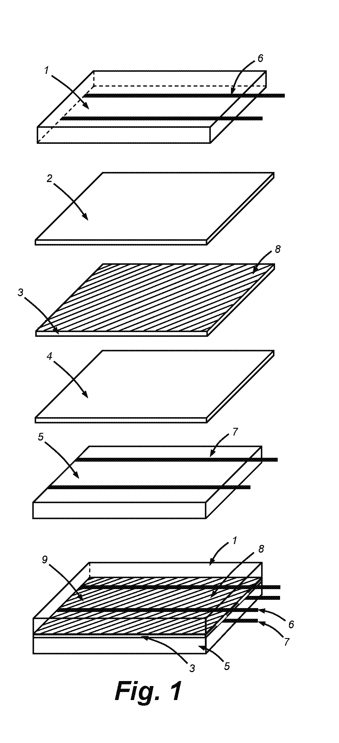
[0044]Single cell encapsulation (SCE) technology according to the illustrative embodiments described below can be a plug-in solution for existing cell and / or module manufacturing lines, which enables the production of lower-cost and higher-performance PV modules, while incorporating a number of desirable features.

[0045]Standard cell manufacturing lines produce photovoltaic cells, which consist of a thin (typically approximately 180 μm) silicon wafer with front and back electrodes. The cells are very fragile and need to be handled with extreme care, and therefore breakage of the cells poses limits on the minimum practical thickness of the cell in a conventional module assembly line. On the other hand, thinner cells require less silicon material and therefore enable lower material cost. Encapsulating the cells as they leave the cell manufacturing line provides strength and protection to the fragile silicon and will enable the handling of ultra-thin (<120 μm) cells without the need for...


PUM


Abstract

A method for encapsulating photovoltaic cells into single functional units is described. These units share the mechanical and electric properties of the encapsulation layers and allow for flexible module architecture to be implemented at the cell level. This enables cost reduction and improved performance of photovoltaic power generation.

Description

RELATED APPLICATIONS[0001]This application is a divisional of copending U.S. patent application Ser. No. 15 / 579,192, filed Dec. 1, 2017, entitled SINGLE-CELL ENCAPSULATION AND FLEXIBLE-FORMAT MODULE ARCHITECTURE AND MOUNTING ASSEMBLY FOR PHOTOVOLTAIC POWER GENERATION AND METHOD FOR CONSTRUCTING, INSPECTING AND QUALIFYING THE SAME, which is a U.S. National Phase of International Patent Application Serial No. PCT / US2016 / 035462, entitled SINGLE-CELL ENCAPSULATION AND FLEXIBLE-FORMAT MODULE ARCHITECTURE AND MOUNTING ASSEMBLY FOR PHOTOVOLTAIC POWER GENERATION AND METHOD FOR CONSTRUCTING, INSPECTING AND QUALIFYING THE SAME, filed Jun. 2, 2016, which claims the benefit of U.S. Provisional Application Ser. No. 62 / 169,938, entitled SINGLE-CELL ENCAPSULATION AND FLEXIBLE-FORMAT MODULE ARCHITECTURE AND MOUNTING ASSEMBLY FOR PHOTOVOLTAIC POWER GENERATION AND METHOD FOR CONSTRUCTING, INSPECTING AND QUALIFYING THE SAME, filed Jun. 2, 2015, the entire disclosure of each of which applications are h...

Claims


Application Information

Patent Timeline
Patent Type & Authority Applications(United States)
IPC IPC(8): H01L31/048H01L31/05H01L31/0224
CPCH01L31/048H01L31/0504Y02E10/50H01L31/022425Y02B10/12H01L31/0508Y02B10/10
Inventor PRETORIUS, JACOB VAN REENENEVERMAN, MICHAEL ROSSFRITZEMEIER, LESLIE G.FERRARA, MARCO
Owner TESSOLAR
Why Eureka
Try Eureka