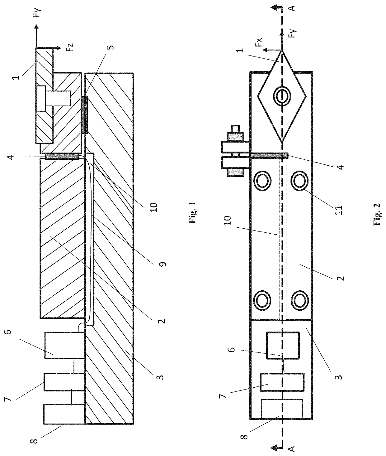
Smart cutting tool system for use in precision cutting

a cutting tool and cutting tool technology, applied in the field of cutting tools, can solve the problems of affecting the characteristics of the machine tool, affecting the installation, and the equipment is too complicated and huge, and achieves the effects of low power consumption, long continuous working time, and high integration

Inactive Publication Date: 2019-11-28
GUANGDONG UNIV OF TECH
View PDF0 Cites 9 Cited by
  • Summary
  • Abstract
  • Description
  • Claims
  • Application Information

AI Technical Summary

Benefits of technology

[0005]Aiming at above shortcomings and application requirements of existing technologies, with the purpose of realizing high speed and high precision real-time monitoring and transmission of weak physical information during ultra-precision cutting process, the present invention provides a smart cutting tool system for use in precision machining based on high speed Bluetooth® transmission, which solve various problems of conventional smart cutting tool systems and has advantages such as high integration, very low power consumption, long continuous working time, high speed transmission, strong real-time capability, more parameters detection, high monitoring precision, low cost and ease of use.

Problems solved by technology

However, the equipment is too complicated and huge and is difficult to install, which also affect the characteristics of the machine tool and adversely affect the rigidity and machining precision of the machine tool.
However, due to the cutting heat in the machining process, information distortion and invalidation may occur.
But these schemes have disadvantages as follows.
The wire data or energy transmission has a limited range of use, because it can be applied only to the machining processes in which cutters remain stationary, but is not available for the machining processes in which cutters move synchronously.
However, on one hand, the transmission distance which is usually less than 5 meters is too short, and on the other hand, the peak rate is approximately 200 kbps and real-time monitoring capability is affected due to the small amount of transferred data per unit time.
For example, existing infrared technology not only is limited to a distance of 3 meters, but also has an acceptance angle seriously limited to 30°.
It cannot be applied to point-to-multi-point transmission and thus has limited applications.
However, WIFI transmission has not only poor data security, but also high power consumption and short battery life and thus cannot be applied to continuous machining process over long periods.
Moreover, the wireless passive detection schemes based on surface acoustic wave use complex equipment and have short transmission distance as low as 0.5 meter.
All schemes disclosed above meet neither the requirements of continuous high-reliable remote real-time wireless monitoring for ultra-precision machining process over long periods, nor the requirements of measurement precision and sensitivity for ultra-precision machining applications.

Method used


Image

  • Smart cutting tool system for use in precision cutting

Examples


Embodiment Construction

[0030]In order to further clarify the purpose, solutions, and advantages of embodiments of the present invention, the embodiments of the present invention will be clearly described below in detail in conjunction with drawings of embodiments. It is clear that the described embodiments are only a part of embodiments of the present invention, not all embodiments of the present invention.

[0031]It should be understood that, as used herein, terms such as “upper” and “lower” for indicating orientation or position relationships are described referring to the orientation or position relationships in the drawings for convenience of description of the present invention, but are not intended to mean or hint that the described device or element must be arranged at a specific position or operated by a specific method at a specific position to limit the invention in any way. Furthermore, terms such as “first”, “second” and “third” are merely illustrative, but are not intended to mean or suggest re...


PUM


Abstract

A smart cutting tool system for use in precision cutting, comprising a cutting insert (1), an upper cutter arbor (2), a lower cutter arbor (3), a first pressure sensor (4), a second pressure sensor (5), a signal processing module (6), a Bluetooth® transmission module (7), and a power supply (8), wherein the cutting insert (1) is fixed to a front end of the upper cutter arbor (2), the cutting insert (1) is provided at its rear end with a microgroove, in which the first pressure sensor (4) and the second pressure sensor (5) are inserted. The cutting tool system solves the problem of mutual coupling of various cutting forces, and has higher sensitivity.

Description

FIELD OF THE INVENTION[0001]The present invention relates to the field of cutting tools, more particularly to a smart cutting tool system for use in precision cutting.BACKGROUND OF THE INVENTION[0002]During machining process, an acquisition of information such as cutting force and cutting temperature is of great significance for optimizing processing parameters of the machining process and improving machining quality. In order to improve surface quality of parts machined by ultra-precision cutting and to efficiently and reliably produce large-sized parts with high surface figure accuracy, real-time state information of the cutting tool during machining process is crucial.[0003]Now, during monitoring and researching of the machining process, the solution which involves integrated force sensor is usually adopted. However, the equipment is too complicated and huge and is difficult to install, which also affect the characteristics of the machine tool and adversely affect the rigidity an...

Claims


Application Information

Patent Timeline
Patent Type & Authority Applications(United States)
IPC IPC(8): B23B25/06B23B27/00
CPCB23Q17/0952B23B25/06B23B27/145B23B2226/315B23Q15/007B23B27/00B23B2260/108B23B2260/128B23B27/1614B23B29/12
Inventor CHEN, XUN
Owner GUANGDONG UNIV OF TECH
Why Eureka
Try Eureka