Motor driving device and motor driving method

a technology of motor driving and motor driving method, which is applied in the direction of winding head prevention/reduction, power cables, cables, etc., can solve the problem that the high frequency leakage current may not be sufficiently suppressed in some cases, and achieve the effect of suppressing the high frequency leakage curren

Active Publication Date: 2019-11-28
FANUC LTD
View PDF0 Cites 6 Cited by
  • Summary
  • Abstract
  • Description
  • Claims
  • Application Information

AI Technical Summary

Benefits of technology

[0009]Each aspect of the present disclosure enables to suppress a high frequency leakage current by canceling high frequency leakage currents among groups.

Problems solved by technology

Therefore, due to such a variety of stray capacitances, the high frequency leakage current may not be sufficiently suppressed in some cases.

Method used


Image

  • Motor driving device and motor driving method
  • Motor driving device and motor driving method
  • Motor driving device and motor driving method

Examples


Embodiment Construction

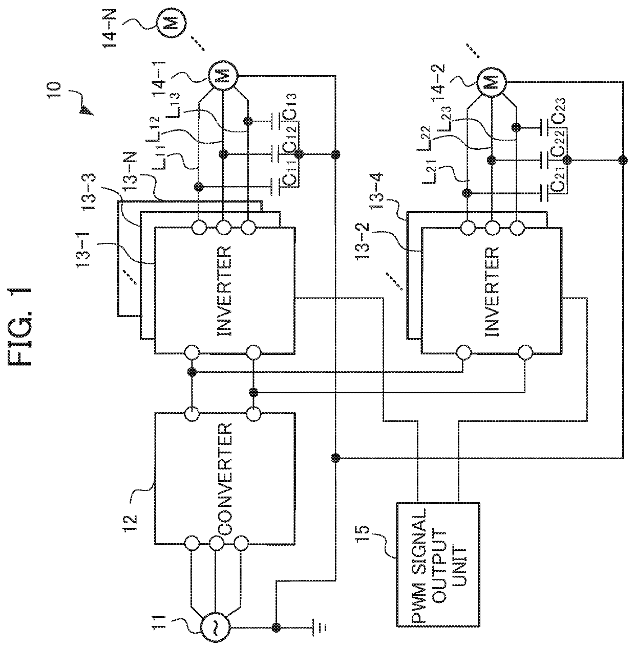
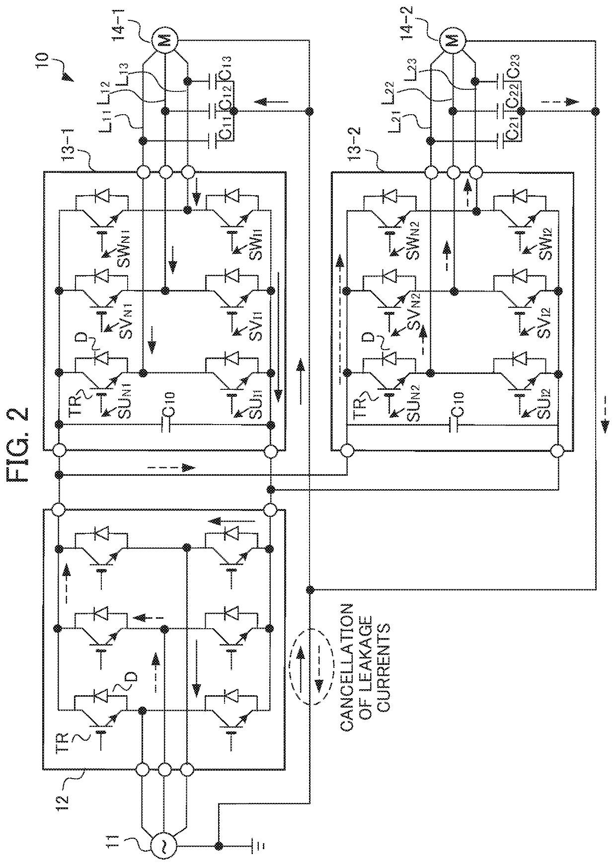
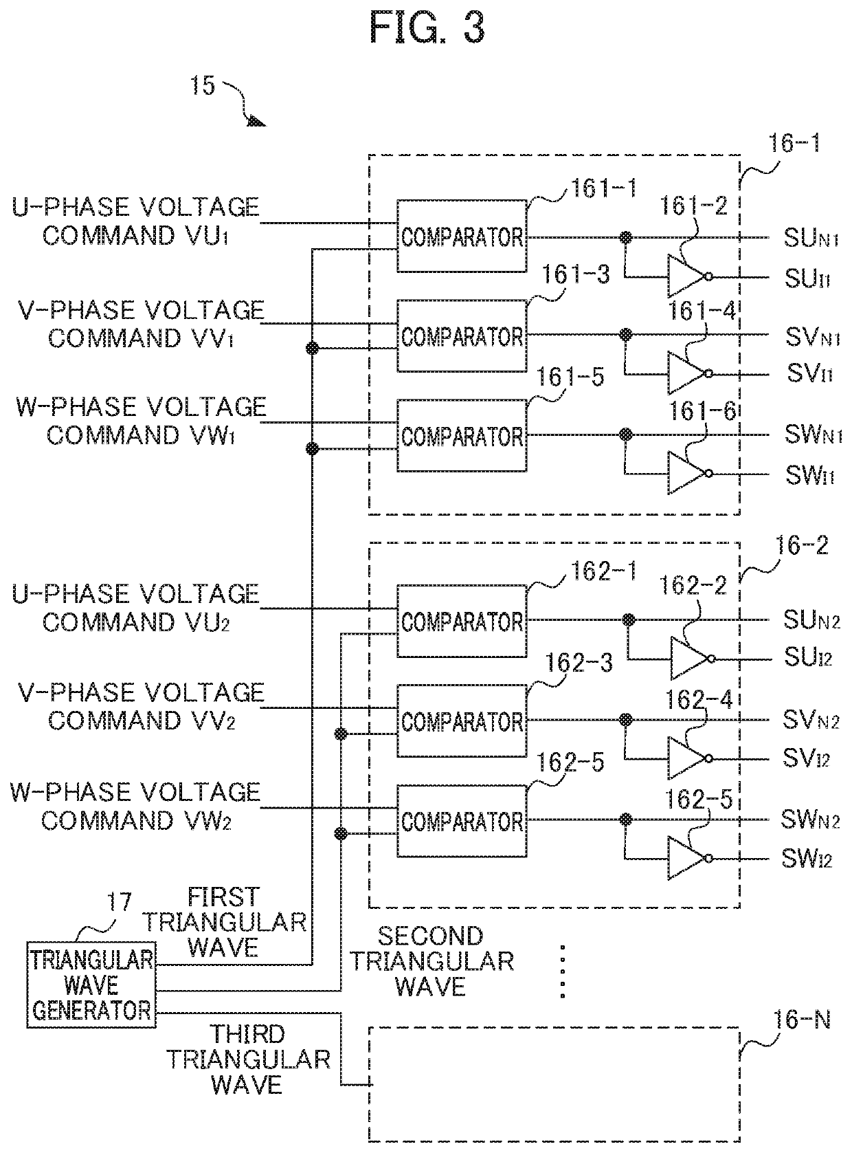
[0015]An embodiment according to the present disclosure will be described below in detail with reference to the drawings. FIG. 1 is a configuration diagram illustrating a motor driving device according to one embodiment of the present disclosure. FIG. 2 is a configuration diagram illustrating the detailed configurations of a converter and inverter of the motor driving device shown in FIG. 1. FIG. 3 is a configuration diagram illustrating the configuration of a PWM signal output unit of the motor driving device shown in FIG. 1. A motor driving device 10 shown in FIG. 1 drives a motor of, for example, a machine tool, a robot, or an industrial machine.

[0016]The motor driving device 10 includes an AC power source 11, a converter 12, N units (N is a natural number equal to or greater than 2) of inverters 13-1 to 13-N, N units of motors 14-1 to 14-N, cables L11 to L13 respectively to cables LN1 to LN3 for connecting the respective inverters 13-1 to 13-N and the motors 14-1 to 14-N, and a ...


PUM


Abstract

A motor driving device includes N units (N is a natural number equal to or greater than 2) of inverters configured to control N units of motors, respectively, a×N units (a is a natural number) of cables configured to allow connection between the N units of inverters and the N units of motors, respectively, and a PWM signal output unit configured to transmit a PWM signal to the N units of inverters. The N units of inverters and the a×N units of cables are divided into M groups (M≤N). The PWM signal output unit outputs the PWM signal for driving at least one inverter belonging to each group of the M groups so that the PWM signals have phase differences shifted by 360 degrees/M among the groups.

Description

[0001]This application is based on and claims the benefit of priority from Japanese Patent Application No. 2018-098946, filed on 23 May 2018, the content of which is incorporated herein by reference.BACKGROUND OF THE INVENTIONField of the Invention[0002]The present invention relates to a motor driving device and a motor driving method.Related Art[0003]As a motor driving device, for example, Patent Document 1 discloses a multi-axis driving system for driving a plurality of motors by a plurality of inverter type driving means for performing switching operation based on a carrier signal for PWM (pulse width modulation). In the case where the inverter type driving means drive the motors, the rapid change of voltage due to the switching operation causes such a phenomenon that a high frequency leakage current flows in a grounding line (a motor case) through a stray capacitance of a motor winding thereof. In order to suppress such a high frequency leakage current, the multi-axis driving sy...

Claims


Application Information

Patent Timeline
Patent Type & Authority Applications(United States)
IPC IPC(8): H02K3/42H02P27/08H02P5/74H02P5/46
CPCH02P5/74H02P27/08H01B9/026H02P5/46H02K3/42H02P27/085H02P29/50
Inventor MATSUMOTO, YASUYUKITATEDA, MASAYAINAGAKI, KEITAROU
Owner FANUC LTD
Why Eureka
Try Eureka