Heat transfer tube and method for manufacturing a heat transfer tube

a heat transfer tube and heat transfer tube technology, applied in manufacturing tools, lighting and heating apparatus, separation processes, etc., can solve the problem that the volume of welding material for the weld ridge is relatively small, and achieve the effect of increasing the angle of each weld, improving the heat transfer rate, and increasing the distan

Active Publication Date: 2019-12-05
VALMET AB
View PDF2 Cites 1 Cited by
  • Summary
  • Abstract
  • Description
  • Claims
  • Application Information

AI Technical Summary

Benefits of technology

[0017]The height of the weld ridge may be higher in tubes fed with spent cooking liquor with higher dry matter content than in tubes for spent liquor with low dry matter content. For example, in a first evaporation effect where the spent liquor fed to the effect is 20% the height of the weld ridge may be about 0.5 mm as this may be sufficient to cause turbulence in the relative low viscosity conditions, while a later evaporation effect fed with spent liquor with dry matter content at 50% may have a height of the weld ridge about 2.0 mm as this may be required to cause turbulence at higher viscosity conditions.
[0018]In a preferred embodiment of the invention, the width of said weld ridge is in the range 0.5-15 mm, preferably 1-10 mm and even more preferably 1.5-5 mm. Keeping the width within this range has the advantage of inducing turbulence in the liquid film by disturbing the film flow.
[0019]In a preferred embodiment of the invention, the weld ridges are inclined in relation to a plane orthogonal to the longitudinal axis of the heat transfer tube and extends helically along at least a portion of the length of the heat transfer tube. The weld ridges are inclined with an angle below or equal to 70 degrees and preferably below or equal to 50 degrees. In some embodiments, the preferable inclination angle is within the range 1-15 degrees, and in other embodiments within the range 15-45 degrees. Such a weld ridge may be applied by a welding head that either revolves around the tube or rotates inside the tube while applying the weld ridge. In one alternative embodiment may at least two welds forming weld ridges be inclined and extend in parallel, which makes it possible to increase the angle of each weld, i.e. to change the pitch, while also increasing the distance, measured in the longitudinal direction of the tube, between weld ridges formed by the respective welds.
[0020]Another embodiment of the invention may include at least two weld ridges that are inclined in relation to the plane orthogonal to the longitudinal axis of the heat transfer tube and arranged crossing each other. Such intersecting weld ridges may improve the heat transfer rate as the falling film is forced to several direction changes, inducing turbulence.

Problems solved by technology

Also, the weld ridges require relatively small volumes of welding material.

Method used


Image

  • Heat transfer tube and method for manufacturing a heat transfer tube
  • Heat transfer tube and method for manufacturing a heat transfer tube
  • Heat transfer tube and method for manufacturing a heat transfer tube

Examples


first embodiment

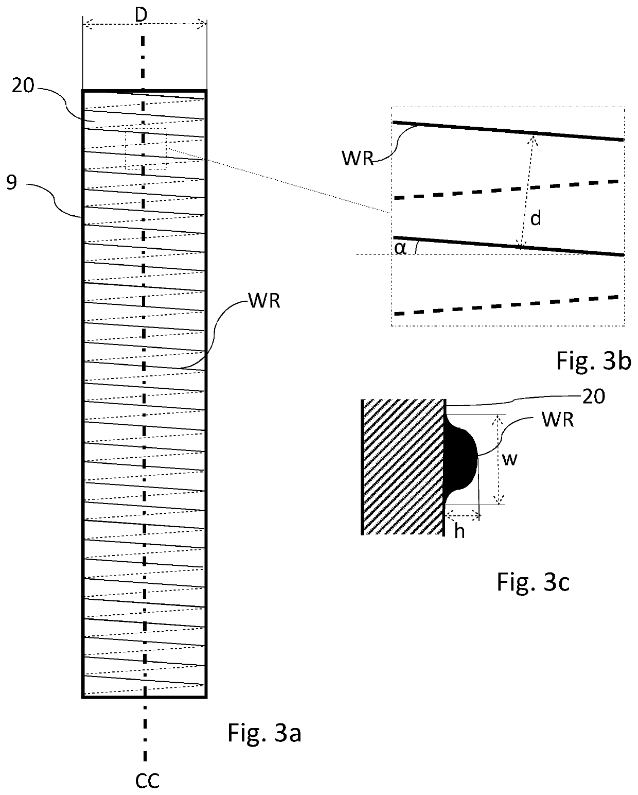
[0051]In FIG. 3a is a heat transfer tube 9 according to the invention shown. In this case is a continuous surface weld applied on an outer falling film surface 20 of the heat transfer tube 9 and forming a multitude of weld ridges spaced apart along the longitudinal axis of the heat transfer tube. It should be understood that the surface weld may be applied instead on the inner surface of a heat transfer tube, if the thin film of spent cooking liquor flows on said inner surface. FIG. 3b shows an enlarged portion of FIG. 3a, and FIG. 3c a detailed cross section of the surface weld.

[0052]In the figures is:[0053]CC the longitudinal axis of the heat transfer tube 9;[0054]d the distance between adjacent weld ridges WR perpendicular to the longitudinal extension of the weld forming the weld ridges WR;[0055]α the inclination angle of the weld ridges WR versus a plane orthogonal to the center axis CC of the heat transfer tube 9, in this embodiment close to 15 degrees;[0056]The distance betwe...

second embodiment

[0059]FIG. 4a shows the heat transfer tube 9 according to the invention, with multiple surface welds applied to form parallel and continuous weld ridges WR. FIG. 4b shows an enlarged part of the heat transfer tube, wherein:[0060]d is the distance between adjacent weld ridges WR perpendicular to the longitudinal extension direction of the welds forming the weld ridges WR,[0061]α is the inclination angle of the weld ridges WR versus a plane orthogonal to the center axis CC of the heat transfer tube 9, in this embodiment about 45 degrees.[0062]The distance between adjacent weld ridges in a direction parallel to the longitudinal axis CC is calculated as d divided by cos α

third embodiment

[0063]FIG. 5a shows the heat transfer tube 9 according to the invention. A surface weld forms a multitude of first kind of weld ridges WR1, identical to the weld ridges WR shown in FIG. 3a, and a crossing butt weld forms a multitude of protruding second weld ridges WR2. FIG. 5b shows an enlarged part of the heat transfer tube 9, and FIG. 5c shows a cross section through one of the second kind of weld ridges WR2. The height h2 and width w2 of the second kind of weld ridges WR2 are of the same magnitude as for the first kind of weld ridge WR1, whereas the inclination angle α2 is somewhat steeper for the second kind of weld ridges WR2 and the distance d2 between adjacent second kind of weld ridges WR2 perpendicular to the longitudinal extension direction of the welds forming the weld ridges WR2 is longer. The distance between adjacent weld ridges along the longitudinal axis is d2 divided by cos α2.


PUM

PropertyMeasurementUnit
distanceaaaaaaaaaa
distanceaaaaaaaaaa
distanceaaaaaaaaaa

Abstract

The invention relates to a heat transfer tube (9) for falling film evaporation having a heating medium surface (21) to be heated by a heating medium, a falling film surface (20) to have spent liquor passing over it, and being made from an iron based high alloy stainless steel material with an alloy content above 16.00% for Chromium and above 1% for Nickel. The falling film surface of the heat transfer tube is equipped with at least one weld ridge (WR; WR1, WR2), said weld ridge having a height (h; h2) in the range 0.3 to 5.0 mm, a width (w; w2) in the range 0.5-15 mm, and an inclination angle (α; α1, α2) versus a plane orthogonal to a longitudinal axis (CC) of the heat transfer tube in a range of 0-70 degrees so that each weld ridge is inclined and extends helically along at least a portion of the heat transfer tube or extend within a plane orthogonal to the longitudinal axis of the heat transfer tube and forms well ridge portions on the falling film surface such that the distance along the longitudinal axis of the heat transfer tube between adjacent weld ridge portions is within the range of 0 to 250 mm. The invention also relates to a method for manufacturing said heat transfer tube.

Description

TECHNICAL FIELD[0001]The invention relates to a heat transfer tube for falling film evaporation of spent liquor. The heat transfer tube has a heating medium surface arranged to be heated by a heating medium, and a falling film surface opposite and facing away from said heating medium surface, which falling film surface is arranged to have spent liquor containing lignin and other dissolved components from cellulosic material and / or inorganics from the cellulosic material and chemicals used passing over it as a falling film while evaporating solvent (mainly water) from the falling film and thus increasing the dry matter content as well as viscosity. The heat transfer tube is made from a sheet metal material, e.g. an iron based high alloy stainless steel material with an alloy content above 16.00% for Chromium and above 1% for Nickel, preferably corresponding to corrosion resistant steel qualities at least like AISI 316 or AISI 304. The invention also relates to a method for manufactur...

Claims


Application Information

Patent Timeline
Patent Type & Authority Applications(United States)
IPC IPC(8): B01D1/06B01D1/30F28F1/34
CPCF28F1/34F28F2275/06B01D1/30B01D1/065B01D1/06D21C11/10F28F1/426F28F2001/428F28F3/044F28F21/083F28F2255/08F28D7/16F28D5/02F28F3/046B23K2101/06B21D22/02B21D51/10D21C11/0007B23K2103/05B23K2101/08B23K11/0073B23K11/16
Inventor OLAUSSON, LARSPETTERSSON, KRISTERAPEL, MARTINGOURDON, MATTIASÅKESJÖ, ANDERS
Owner VALMET AB
Why Eureka
Try Eureka