
Biopsy system for enhanced tissue harvesting

a biopsy system and tissue harvesting technology, applied in the field of biopsy systems, can solve the problems of increasing the likelihood of complications such as bleeding or even death, increasing the number of procedures, and increasing so as to improve diagnostic ultrasound guidance, reduce the number of passes, and harvest large volumes of tissue

Active Publication Date: 2019-12-26
THE ARIZONA BOARD OF REGENTS ON BEHALF OF THE UNIV OF ARIZONA +2
View PDF0 Cites 8 Cited by
  • Summary
  • Abstract
  • Description
  • Claims
  • Application Information

AI Technical Summary

Benefits of technology

This patent describes a biopsy system that uses a cutting mechanism to remove tissue samples from the body. The cutting mechanism can use various methods such as cutting, electromagnetic force, pressure, thermal energy, or vibrational energy to achieve this. The system also includes a mechanism for better visualization and location of the needle in the tissue using ultrasonic vibrations. The needle can have a conductive interior or have additional electrodes to improve diagnosis or manufacturing. The system can also have multiple electrodes on the needle for better guidance and reduction of complications. Overall, this patent presents an innovative biopsy system with unique technical features that can improve the efficiency and accuracy of tissue removal.

Problems solved by technology

However, more passes by the needle increases the likelihood of complications such as bleeding or even death.
In addition, an increased number of passes may mean longer procedural times and longer post-procedural monitoring.
Another means of obtaining more tissue is the use of a larger needle, but bigger needles also carry increased risk of complications, such as bleeding or other organ-specific complication (e.g. pneumothorax, etc).
While the current standard of external imaging-based guidance through, for example, x-rays / fluoroscopically / CT, medical ultrasound, or MRI, is very powerful, there are limitations.
As an example, CT-guidance for lung biopsies is fraught with difficulties.
However, many patients cannot reasonably hold their breath for the duration of the scan, let alone the brief time for interpretation of the scan including triangulating the trajectory of the needle and the target and then the time it takes for appropriate advancement of the needle to the target.
Furthermore, despite the most proficient percutaneous intervention, complications related to bleeding do occur from the needle violating blood vessels.

Method used


Image

  • Biopsy system for enhanced tissue harvesting
  • Biopsy system for enhanced tissue harvesting
  • Biopsy system for enhanced tissue harvesting

Examples


example 1

[0158]A non-limiting example of the biopsy needle device prototype of the present invention, herein referred to as the Triopsy needle, is shown in the top image of FIG. 26A. The inset provides the details of the 3D prototype. The 3D printed Triopsy needle is attached to a syringe after having aspirated a tofu-tissue model. The bottom image of FIG. 26A shows an exact-sized hollow needle without the dome, which is a model of standard full-core biopsy needles. FIG. 26B shows the result of 4 trials with the various biopsy needle types having been inserted equal depths and spun 5 times clockwise under different relative vacuum pressures. Significantly more tissue was harvested using the novel Triopsy-type needle (two-tailed paired t-test p2>0.9, p<0.01) between mm of model tissue aspirated into the tubing and dry weight of the harvested tissue not shown.

[0159]FIG. 26C shows a theoretical comparison of amount of tissue harvested using current industry standard biopsy needles and using the...

example 2

ocedure

[0160]The biopsy needle includes a sheath through which biopsy device and other accessories can be inserted. Accessories include electrocautery device, radioopaque marker insertion device, tissue sealant injector, device to inject filler material, etc.[0161]1. Prepare device: use syringe to apply suction; turn stopcock to preserve vacuum.[0162]2. Use ultrasound guidance to advance needle / outer sheath into patient and position at distal end of tumor.[0163]3. Use mechanics to retract outer sheath to expose expandable curved cutting blade and needle lumen.[0164]4. Use stopcock to apply vacuum to needle lumen.[0165]5. Rotate device to collect tissue biopsy (manual, motor driven, spring driven).[0166]6. Stop rotation and reposition outer sheath.[0167]7. Collect biopsy using vacuum and store in collection chamber[0168]8. Use stopcock to close vacuum[0169]9. Disengage outer sheath (luer adapter) from biopsy needle unit, if desired[0170]10. Remove needle unit; sheath (optionally) rem...

example 3

ocedure Triopsy Edge Complex Device

[0181]1. Apply grounding pad to patient and attach to electrocautery unit. Attach electrocautery unit to biopsy device.[0182]2. Insert needle and sheath into patient under external imaging (e.g. ultrasound) visualization.[0183]3. Position within the tumor, preferably distally for pullback biopsy.[0184]4. Press start button to activate device. Solid green ready light appears.[0185]5. Press start button to begin biopsy process. Green light begins to blink.[0186]6. Outer sheath retracts.[0187]7. Vacuum starts.[0188]8. Electrosurgery signal directed to cutting blade.[0189]9. Needle begins to rotate for n rotations (n=1-20).[0190]10. Electrosurgery inactivated.[0191]11. Outer sheath extends distally.[0192]12. Vacuum continues to collect tissue.[0193]13. Vacuum turns off.[0194]14. Solid green light reappears-ready light.[0195]15. Reposition biopsy device to starting position.[0196]16. Depress and hold button to activate electrocautery.[0197]17. Inactivat...


PUM


Abstract

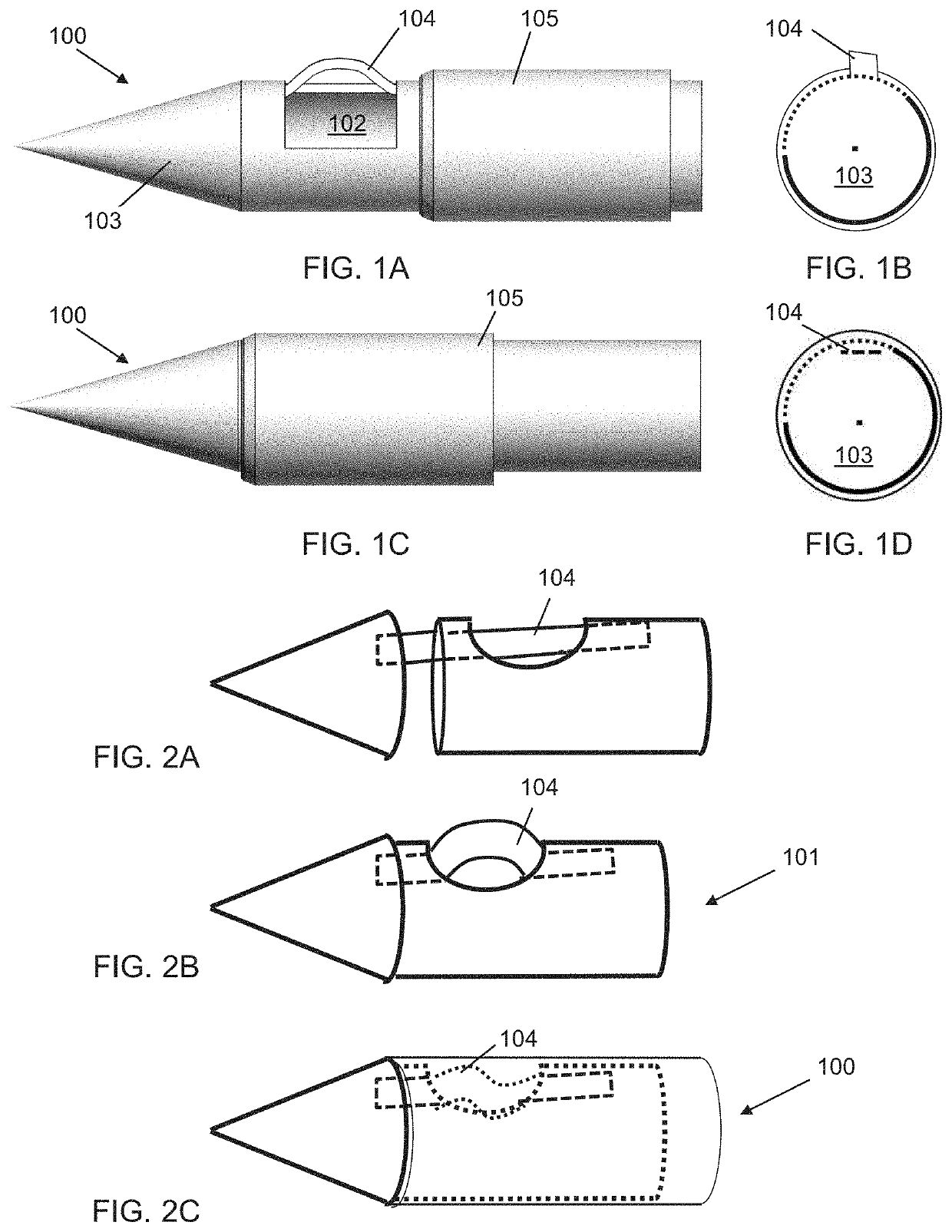
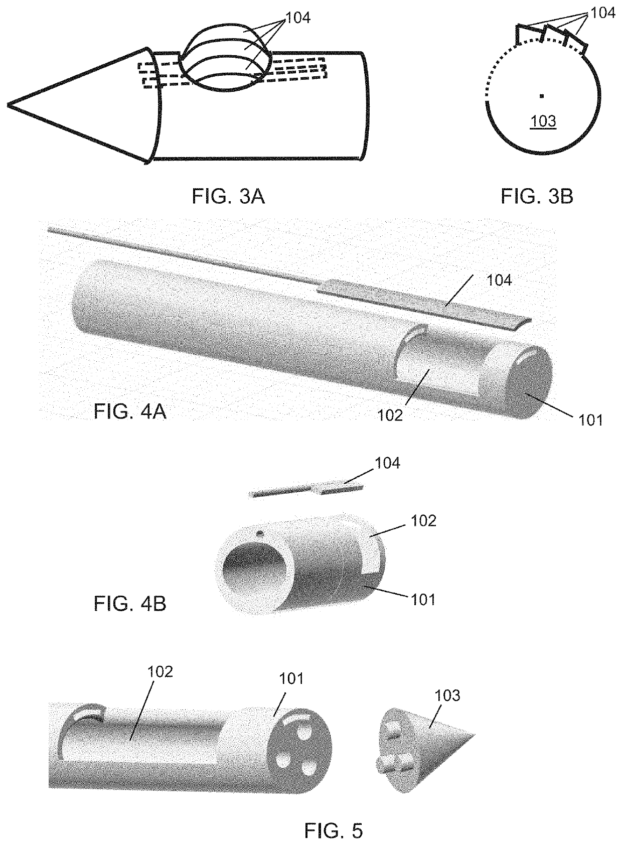
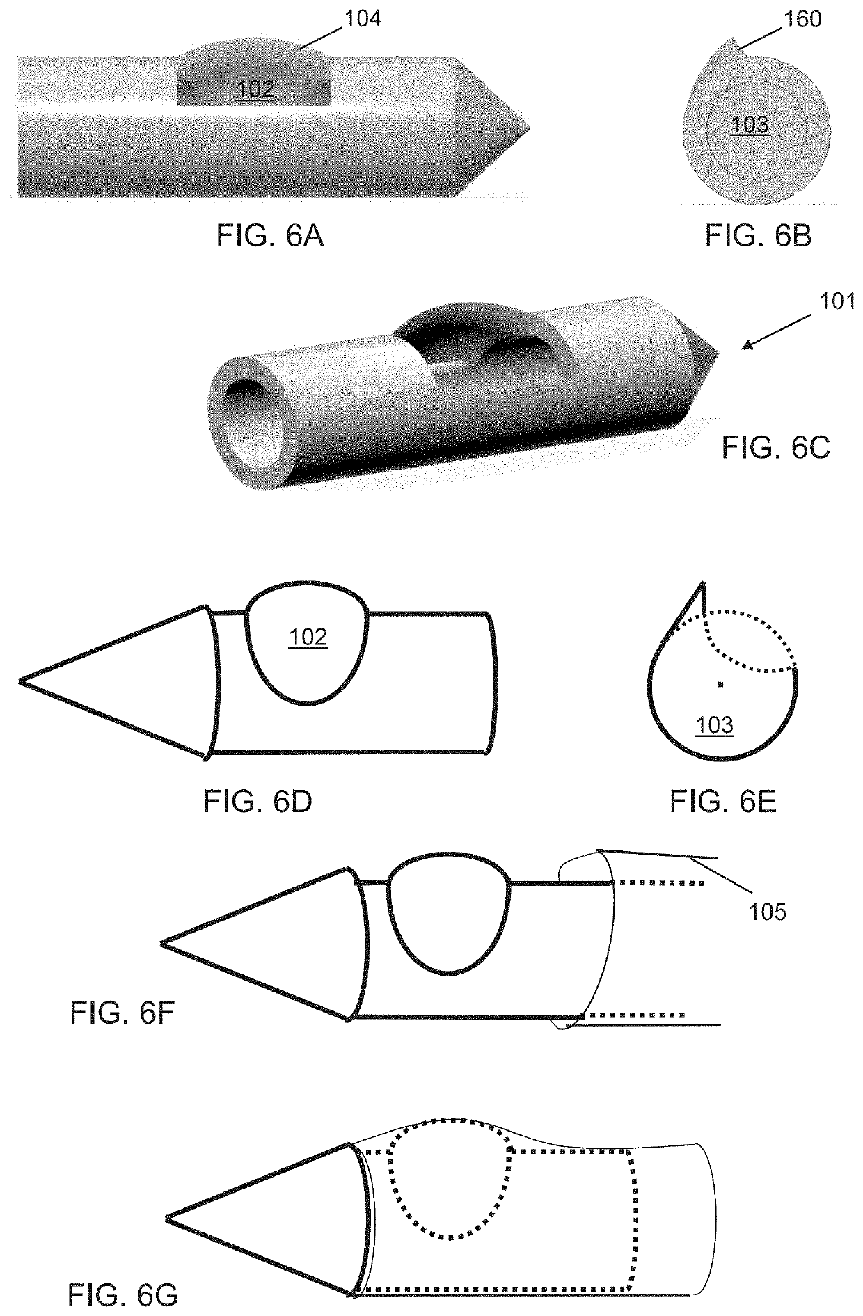
A biopsy system for harvesting larger volumes of tissue as compared to standard core biopsy needles. The system has a needle with a lumen, an aperture disposed at the distal end of the needle and connected to the lumen, and a cutting mechanism adapted to cut tissue. When the needle is rotated after it is inserted into a target tissue, the cutting mechanism cuts from the tissue and directs the cut tissue portions into the lumen. Multi-bioimpedance measurements are used to guide a needle and direct the application of electricity for cauterizing tissue.

Description

CROSS REFERENCE[0001]This application is a continuation-in-part and claims benefit of PCT / US2018 / 020851 filed Mar. 5, 2018, which claims benefit of U.S. Patent Application No. 62 / 466,549 filed Mar. 3, 2017, the specification(s) of which is / are incorporated herein in their entirety by reference.FIELD OF THE INVENTION[0002]The present invention relates to devices and methods for performing biopsies, more particularly, to a biopsy system featuring a deployable mechanism for cutting biopsy samples and cauterization. The present invention further provides multi-bioimpedance measurements for guiding a needle and directing electrical coagulation.BACKGROUND OF THE INVENTION[0003]In patients suspected of having a disease with potentially harmful treatments, such as cancer, a small sample of tissue, termed a biopsy, is needed to make a correct diagnosis. In some cases, a biopsy is used to identify specific cancer characteristics to allow for a more personalized therapy. Large amounts of tissu...

Claims


Application Information

Patent Timeline
Patent Type & Authority Applications(United States)
IPC IPC(8): A61B10/02
CPCA61B2010/0208A61B10/0275A61B2010/0225A61B10/0283A61B10/0266A61B2018/00595A61B10/02A61B2018/00577
Inventor LARSON, MICHAEL C.HENNEMEYER, CHARLES T.
Owner THE ARIZONA BOARD OF REGENTS ON BEHALF OF THE UNIV OF ARIZONA
Learn More